24 hour delivery timer
24 hour delivery timer
24 hour timer delivery method Often we need a 24 hour timer inside the electrical panels to perform the function of operating a load for a specified period of time over 24 hours.
A timer or 24 hour timer is used in outdoor lighting units within a specified range of time, It is also used to irrigate agricultural crops by operating a surface or submersible water pump for a specified time within 24 hours.
In this article, we will learn about the components of a 24 hour timer. How to set it and how to connect it.
24 hour timer components
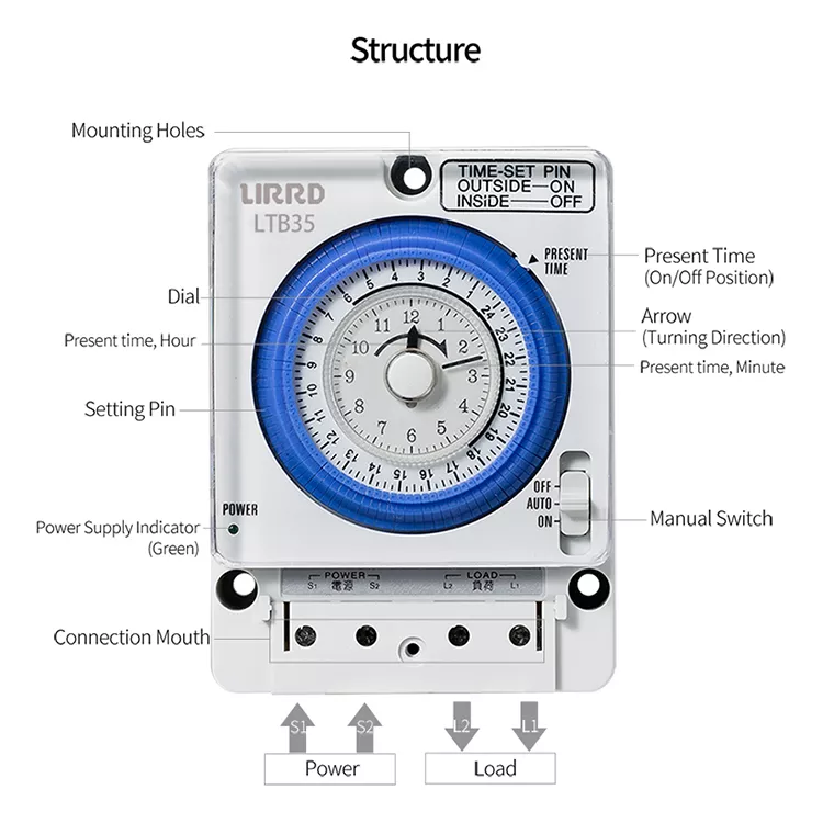
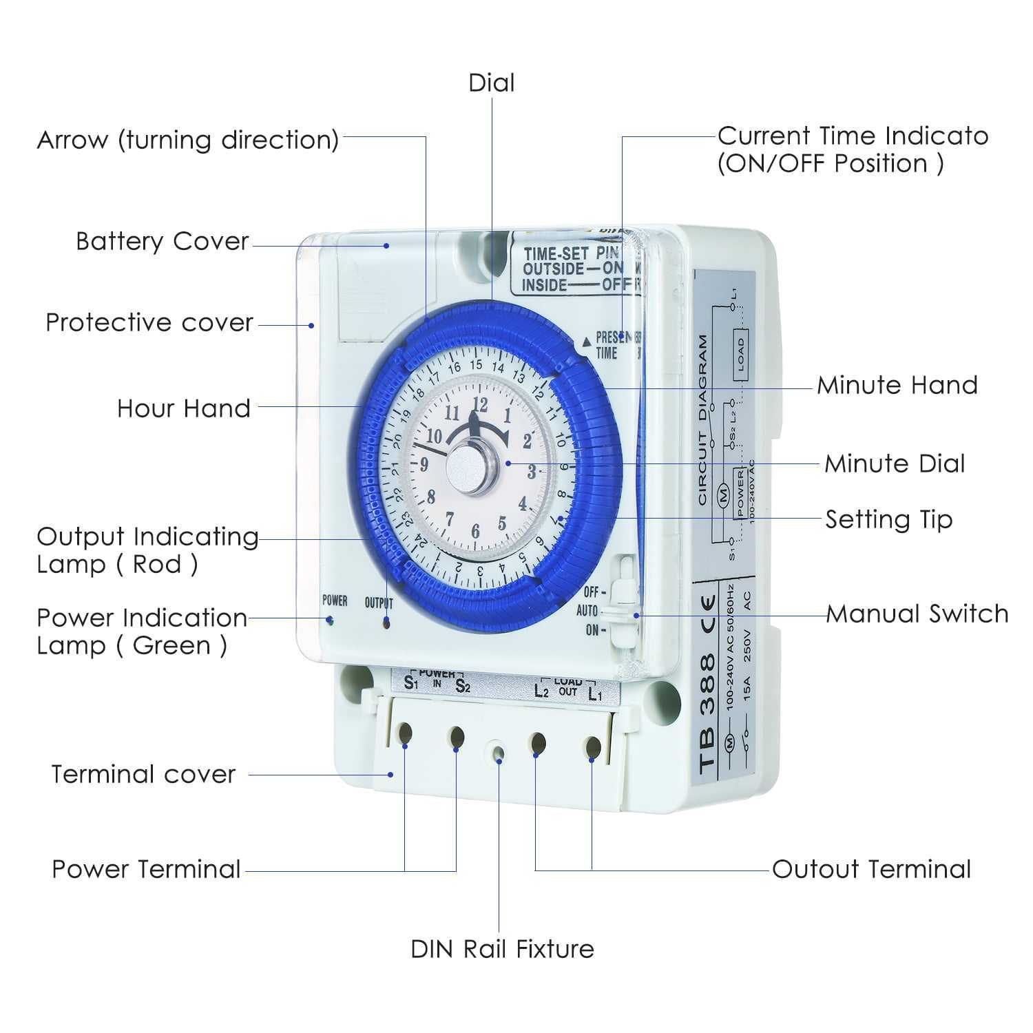
The timer consists of the front end on the following points:
Center ring: Through it, the connection and disconnection time can be set when the timer is set to the automatic connection and disconnection mode.
Transfer points, including:
- Mode 0: The timer is connected to the normal state, That is, the common point is connected with the closed point in the normal state (NC).
- Mode 1: when converting to it, The timer connects the common point with the open point in the normal state (NO).
- clock code: when placed on it, The timer will work automatically based on the times you set with the carousel.
And the points of connection or disconnection of the current to the load or the contactor coil change based on the mechanism for setting the specified times throughout the 24 hours.
 24 hour timer components
Timer connection points
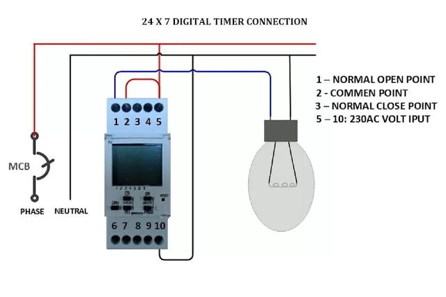
The points L and N: Two dedicated to feeding the timer with a 1 phase electricity source.
point number 2: A common point through which the transfer between points 3 and 1.
Point #3: As it is noted that it is connected in the normal state with common point No. 2, Therefore it is called NC i.e. connected in its natural state.
Point #1: It is not connected in the normal state and is therefore called NO, It connects when the set time is reached to operate an electrical load.
The timer is adjusted through the rotating ring. The timer is set to the current time. And then set the hours of contact and dismissal over 24 hours.
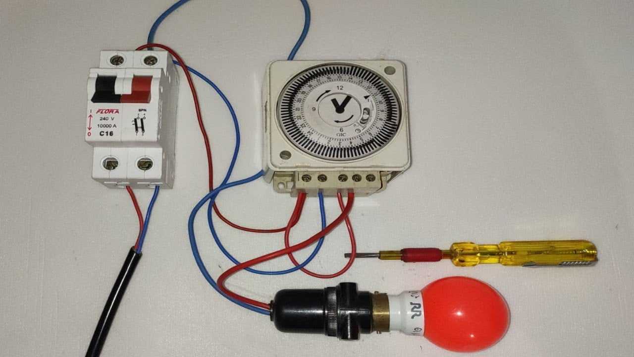
24 hour timer delivery method
- The beat line connects to point L, While the Neutral line has a point N.
- Connect a line from point L with common point No. 2.
- A line is connected from point No. 1 to the load phase or contactor coil A1 whose operation is to be controlled, While the load neutral line or the contactor coil A2 is connected with point N directly.
- Connect a line from point No. 3 to the line that won the other load in case you want to run a second load, or to a signal bulb, While the load neutral line connects with point N.
electrical circuit components
electrical circuit components
We are pleased to have you visit our pages on social networking sites, where we publish exclusive offers on our website.
Our Facebook page here .
Our Twitter account is here .








Leave a Reply
You must be logged in to post a comment.