How to measure voltage and amperes
How to measure voltage and amperes
 How to measure voltage and amperes
How do you measure electrical voltage? There are two types of voltages that electrical and electronic circuits operate on: alternating voltage and direct voltage.
There is a device dedicated to measuring voltage in practice, and each type of voltage has a method that differs from the other, meaning when measuring direct voltage, the multimeter must be set to the direct voltage measurement mode to perform the measurement process, and so on with alternating voltage.
The aim of this topic is to explain how to measure electrical voltage practically and using a multimeter, which is also called a multi-function measuring device.
What is a multimeter?
It is an important device that any technician working in the field of electricity, electronics, batteries, solar energy, and electrical control cannot do without.
This device is used to measure most electrical parts, such as: checking home and industrial electricity networks, checking source voltage and resistors, and all electronic parts such as: resistors, transistors, diodes, and many, many different parts.
What we mean in this topic is to explain in detail how to measure direct current and alternating current electrical voltage.
Multimeter sensors
The difference between a manual and an automatic multimeter
 How to measure direct voltage (DC)
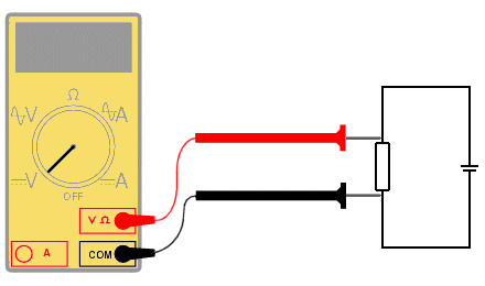
There are several important steps that must be followed in order to measure the continuous voltage of the battery, for example as follows:
- Place the device’s red probe into the port designated for voltage, which is symbolized by the letter (V).
- Place the black probe into the common (COM) port.
- Turn on the multimeter by pressing the power key if it has a power key, and if it does not, all you have to do is move the cursor key only for it to work.
- Place the multimeter pointer on the constant voltage symbol “Volt” (V).
- If the multimeter is of the manual adjustment type, that is, the voltage measurement range is controlled manually, place the pointer at a voltage value higher than the battery voltage value you expect or the value written on the surface of the battery.
- Place the red probe of the multimeter on the positive (+) terminal of the battery, while the black probe on the negative (-) terminal of the battery.
- The battery voltage reading will appear on the device’s screen, and if the reading value is approximately the same as the voltage written on the battery, this indicates that the battery is good.
Constant voltage measurement method (battery voltage)
How to measure alternating voltage (AC)
Follow these steps:
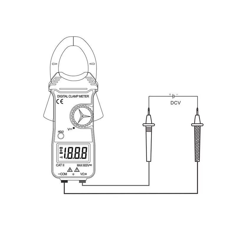
- Place the red probe in the voltage port (V).
- Place the black probe into the COM port.
- Turn on the multimeter, place the scale switch on the alternating voltage with a sine wave drawn on it and the letter (V) next to it.
- Place the two multimeter probes (red and black) in parallel with the household electrical socket (vase and socket) without paying attention to the polarity, because it does not have polarity like a battery.
- You will be shown the source voltage value in AC voltage.
How to check step-down transformers
How to check step-down transformers
How to check step-down transformers: We often see electrical transformers in most electronic boards, the most famous of which are step-down transformers.
In this context, we will learn about a simplified method for checking any small voltage-reducing transformer that you may want to service after disconnecting its terminals from the electronic board.
Step-down transformers
You usually find in most electronic devices, such as radios, televisions, battery chargers, and other electronic boards, an important element called a step down transformer.
The voltage-reducing transformer comes with four or five terminals, and you may find more than that. What we need to examine is the voltage-reducing transformer with four terminals (two terminals, primary coil – two terminals, secondary coil).
Four-pin step-down transformer
The two ends of the primary coil are called the input, while the two ends of the secondary coil are called the output. The difference is between a transformer designed with four terminals, which has two input terminals and two output terminals, while a five-terminal transformer has two input terminals (primary coil) and three output terminals (secondary coil).
Five-pin voltage reducer coil
Step-down transformer function
The basic function of the step-down transformer is to reduce the voltage of the 220VAC/110VAC power supply,
To a lower voltage value in order to supply the entire circuit or a specific part of the electronic circuit.
We cannot fail to note that the transformer only lowers the voltage while keeping the current alternating.
Steps for checking step-down transformers
The process of examining step-down transformers is based on the following points:
- Ensure that the adapter is not connected to the electricity source.
- Disconnect the transformer if it is connected to an electronic circuit.
- When examining the transformer, the resistance of the primary coil and the resistance of the secondary coil must be measured.
- Turn on the multimeter and place the key indicator on the resistance symbol.
- If the device has a reading scale, set a resistance value of 1k, or 200 ohms if the reading appears at a small value.
- Place the probes of the multimeter on both ends of the primary coil, regardless of polarity.
- The device reading appears to be in the range of hundreds or a few tens of ohms.
- While when measuring the resistance of the secondary coil by placing the probes on its ends, you will see a reading that is much smaller and in the range of ohms (less than ten ohms).
- The transformer is damaged if the resistance of the primary or secondary coil is very large, i.e. an open circuit, or zero ohms, i.e., a short circuit.
In line with what was mentioned in the examination steps, a reading of 399 ohms appeared when measuring the resistance between the two ends of the primary coil.
While when measuring the resistance of the secondary coil, we got a reading of 2 ohms.
How to check the primary file
How to check the secondary file
We conclude from the above that the resistance value of the primary coil is always greater than the resistance value of the secondary coil, noting that these values may differ by the number of turns of both the primary coil and the secondary coil.
 How do you measure amperes in practice?
How-to-measure-amps-in-practice
How do you measure the ampere? In practice, the electric current that is measured in the ampere unit is considered one of the important electrical units that is not devoid of any electrical or electronic circuit.
All circuits carry electrical current in the form of direct current or alternating current, depending on the type of current and circuit.
This topic aims to explain how to measure amperes in practice for any electrical circuit that you may want to measure using a multimeter that is set to the ampere measurement mode.
Multimeter device
What is the unit ampere?
The ampere unit is considered one of the basic quantities and is widely used in electrical circuits, and it is the unit of measuring electric current.
Electric current can be defined as the rate of flow of electrons in a circuit from one point to another through a conductor.
The unit of electrical current, “ampere,” is symbolized by the letter (A).
How do you measure amperes?
Before going into the practical details, it is necessary to learn about the most important things that you must know about measuring the amount of ampere that flows within the circuit.
As we know, when measuring the resistance value, source voltage, and battery, the terminals of the multimeter probes are connected in parallel with the elements to be tested.
But this does not happen in the same way when measuring amperes in a circuit.
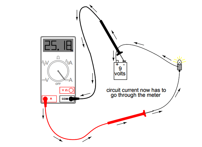
The ampere is measured by connecting the two ends of the multimeter device (red and black) in series with the item to be measured, by separating the path you want to measure, as shown in the simplified figure.
How to connect an ampere meter to a circuit
Steps to measure amperes in practice
- Place the red multimeter probe into the amp or milliamp port if the expected value is less than 200 milliamps.
- Place the black probe into the COM port.
- Turn on the multimeter and place the grading switch on symbol (A), so that it is on direct current (DC) if the circuit is powered by direct current, or on alternating current (AC) if the circuit is powered by alternating current.
- Now we will check or measure the amperage of the lamp connected to the battery.
- Disconnect the positive wire connected to the battery positive and the lamp positive terminal.
- Place the red probe tip of the measuring device with the positive of the battery, while the black probe tip place it on the positive tip of the lamp so that the measuring device is connected in series within the circuit.
- A value in amperes will appear in front of you on the reading screen of the multimeter, which is the amount of current that will flow for the lamp to work.
How to practically measure amperes using a multimeter
Steps to measure AC loads
When measuring the amps of a refrigerator compressor, fan, or air conditioning unit, it is always preferable to use a Clamp Meter, because it measures the load amps without disconnecting the power line.
How to measure amperes using a clamp meter
Correct use of the clamp meter
There is a clamp meter on the market that only measures alternating current, and another that measures direct and alternating current.
Calculate the total resistance of the circuit
Calculate the total resistance of the circuit
Calculating the total resistance of the circuit. The step of calculating the equivalent resistance of the circuit is one of the most important steps
Which enables us to know the total value of the sum of the resistors connected to the electronic and electrical circuit.
Resistors in electronic and electrical circuits are connected in series, parallel, or both.
The importance of calculating the total resistance of the circuit came to know the value of the equivalent resistance, the total current of the circuit, and the voltage applied to it.
Follow this article with us to learn how to calculate the total resistance of a circuit step by step.
 Series circuit for resistors
The series circuit is characterized by being single-pass, easy to connect, and the process of adding the resistors is done to obtain the total equivalent resistance of the circuit.
How to calculate the total resistance value of series circuits
- Sum the resistors connected in series
The sum of the resistors connected in series in the circuit is equal to the equivalent resistance, as the current passing through the resistors is a constant value.
A series circuit containing a 3Ω resistor, a 6Ω resistor, and a 9Ω resistor is as follows:
Series circuit for resistors
The total equivalent resistance of the circuit is:
= 3 + 6 + 9 = 18Ω
- Finding the value of resistance using Ohm’s law
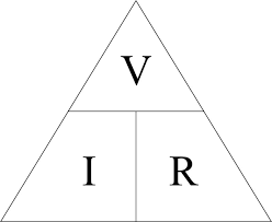
Sometimes there are some unknown values, and from here we resort to using Ohm’s law, which combines the relationship between resistance, voltage, and electric current.
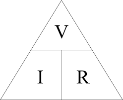
Ohm’s Laws Triangle for Voltage, Current and Resistance
For example:
Series circuit for a group of unknown resistors. Find the equivalent total resistance for this group if you know that the source voltage is 12V and the current passing through the circuit is 10A.
From Ohm’s law, we rearrange the formula V=IR in order to calculate the total resistance, so that the law becomes as follows:
R = V / I
whereas:
R: resistance.
V: voltage.
I: current.
Therefore, the value of the unknown resistance = voltage / current
= 12 / 10 = 1.2Ω
Parallel circuits for resistors
The resistors branch off into several paths and then these paths meet together to complete the circuit
The current flowing through these paths is distributed according to each resistance connected to the circuit.
Calculating the total resistance value of parallel circuits
- Collect resistors connected in parallel
Every parallel path in the circuit carries a current
Electrical based on the value of the resistance placed in this path, and you can calculate the value of the equivalent total resistance RT for the sum of the resistors in parallel as follows:
whereas:
R1: The symbol indicates the resistance value in the first branch.
R2: The symbol indicates the resistance value in the second branch.
R3: The symbol indicates the resistance value in the third branch.
Rn: The symbol indicates the last branch of resistance.
Example: A parallel circuit containing a 3Ω resistor, a 6Ω resistor, and a 9Ω resistor is as follows:
The total resistance of the circuit is equal to:
- Finding the value of resistance using Ohm’s law
Sometimes there is an unknown resistance value in parallel circuits.
Here we resort to Ohm’s Law, which combines the relationship between resistance, voltage, and electric current, which enables you to calculate the total resistance of the circuit.
As it is known that the voltage applied to each branch is a constant value.
The value of the current in the circuit is distributed among all branches of the circuit.
In order to calculate the value of the total resistance of the circuit, we must know the value of the current and total voltage of the circuit using Ohm’s Law.
Example: A parallel circuit with a voltage of 5V and the total current passing through the circuit is 4A. Calculate the value of the total resistance.
From Ohm’s law, we rearrange the formula V=IR in order to calculate the total resistance, so the law becomes as follows:
R = V / I
= 5 / 4 = 1.25Ω
Law of electric potential difference
Law of electric potential difference
The law of electric potential difference, electric potential is considered one of the basic electrical standard quantities in the principles of electricity and electronics.
The reason we need a voltage difference in the circuit is to ensure the flow of electric current, as it works to push the current charges in the circuit.
Let’s learn about the law of electric potential difference, and what it requires in electrical and electronic circuits.
What is electrical voltage?
Also called potential difference or electromotive force,
The potential difference between two points in a conductor is simply expressed by the amount of work needed to be done in order to transfer one coulomb of charge from one point to another point.
In order for electrical charges to be transferred, there must be an electrical potential difference that represents the force that drives these charges to move from one place to another within the conductor.
Unit of measurement of potential difference
In most circuits, voltage is symbolized by the symbol V, while its unit of measurement is voltage, also symbolized by the symbol V, and electrical voltage is measured with a voltmeter.
 Law of electric potential difference
The terms electric potential and electromotive force express the same quantity.
As we explained previously, voltage depends on work and charge.
Work expresses the force necessary to move the charge from one point to another within the circle. It can be calculated as follows:
Electric potential = work x charge
whereas:
Electrical voltage is measured in volts (V).
Work is measured in joules (J).
Charge is measured in coulombs (C).
It can be said that the difference in voltage in any circuit causes the flow of current (charges).
Where the German scientist noticed that there is a direct relationship between the voltage difference and the current,
As the potential difference between the two points increases, the current passing through the resistance increases.
While the relationship between the resistance value and the current is inverse.
The relationship can be expressed as follows:
Voltage difference (V) = Current (I) x Resistance (Ω).
whereas:
Current is measured in amperes and is symbolized by the symbol (A).
Resistance is measured in ohms and is represented by the symbol (Ω).
Law of electric potential difference
Example of the law of electric potential difference
A light bulb has a resistance of 5 ohms and consumes a current of 2 amperes. What is the value of the potential difference applied to the two ends of the light bulb?
Circuit
the solution:
Voltage difference (V) = Current (I) x Resistance (Ω)
= 2 amps x 5 ohms = 10 volts
 To know our latest products and special offers, please subscribe to our social media pages:
Our Facebook page=> Gahzly store
Our Twitter page=> Gahzly store




Leave a Reply
You must be logged in to post a comment.