Star Delta circuit and its connection
Star Delta circuit and its connection
The Star Delta circuit and its connection. The Star Delta circuit is one of the most important circuits that all specialists in the field of electricity and electrical control systems should know. Given the importance of the circuit, we have created a dedicated article that explains the Star Delta circuit in detail, step by step, to make it easier for those interested in this field to understand the circuit.
Connecting the star delta motor
Before starting to learn the Star Delta circuit, you must first learn about the external connection of the motor. Any 3-phase, single-speed motor has a beginning and an end for each phase, and the six terminals are symbolized by internationally recognized symbols as follows:
| beginning | end | |
| First win | U1 | U2 |
| The second victory | V1 | V2 |
| The third victory | W1 | W2 |
In order to connect the Star and then Delta motors, we need to connect the motor terminals to an external control circuit consisting of 3 contactors, a timer, and on and off compressors.
If a star is connected, the motor operates at the highest voltage registered on the motor structure and draws a lower current. For example, if the motor says 220/380 volts, 3/1.7 amps, this means that the lower voltage connects to delta and the higher voltage connects to star.
Star delta circuit rules
Star circuit voltage and current
Star voltage = delta voltage x root of three
Star current = delta current ÷ root of three
Delta circuit voltage and current
Delta voltage = Star voltage ÷ root of three
Delta current = Star current x root of three
Star delta circuit components
The Star Delta circuit consists of the following:
- Three contactors (star contactor, delta contactor, main contactor).
- Overload: Its mission is to protect the motor from high current.
- Electrical timer: Used to switch the motor terminals from star position to delta position.
- Compressor running (NO).
- Separator compressor (NC).
Explanation of the star delta circuit
When the start button is pressed, the control current reaches the main contactor coil (KM3), the timer (K1T) and the contactor star coil (KM1).
The timer (K1T) starts counting down according to the set duration, and after the timer expires, the timer changes its contacts from point (NC) to point (NO).
When the timer changes its contact points, the current is disconnected from the Contactor Star coil (KM1) and the current reaches the Delta Contactor coil (KM2) as a result of connecting the closed point contact taken from the Contactor Star (KM1), and simultaneously the auxiliary point (KM1) is disconnected.
When the stop compressor is pressed, the power to the electric motor is cut off.
The difference between a star circuit and a delta circuit
The difference between a star circuit and a delta circuit. Star delta circuits are considered one of the most important circuits that reduce the starting current of electric motors.
Star Delta circuits are designed according to the capabilities of the engine, so that the temperature of the contactor points does not rise, or the engine burns out as a result of poor connection, failure to take into account the appropriate capabilities, or incorrect connection to the electric motor windings.
Follow this article with us to learn the difference between the Star Circle and the Delta Circle and the function of each one.
Connecting a star circuit
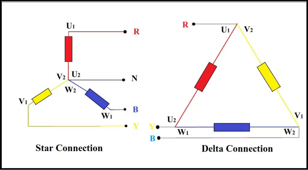
The Star circuit contains three coils, each coil has two terminals, a beginning and an end, where the coils are connected as follows:
- Connecting all the beginnings or ends of the coils together in order to output one end is called the neutral (N).
- Connect each end of a coil to a line from one of the three phase lines as follows:
1. The first phase line (R) with the motor coil terminal (1U) or (2U).
2. The second phase line (S) with the motor coil terminal (1V) or (2V).
3. The third phase line (T) with the motor coil terminal (1W) or (2W).
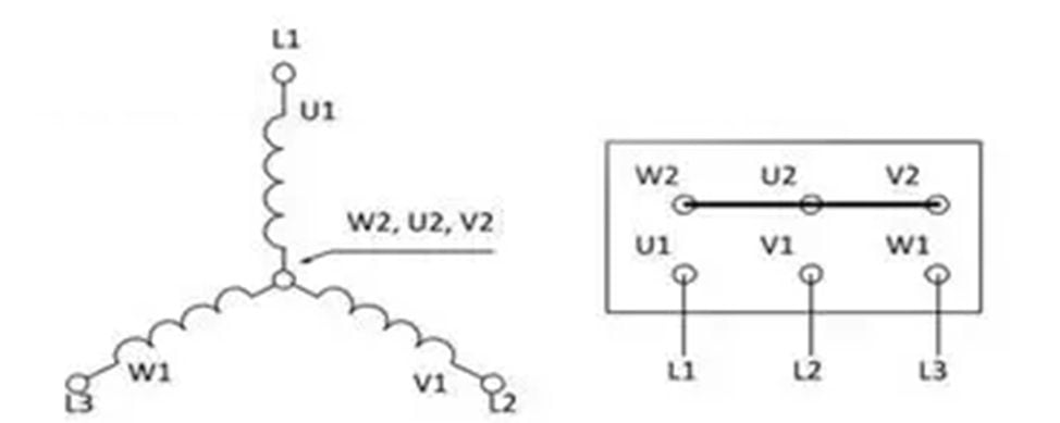
Star circle analysis
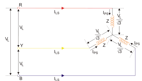
Star circle properties
- line current (ILS) is equal to phase current IPS
- The line voltage can be found using the following equation:
- The phase voltage can be found using the following equation:

- The phase current can be found using the following equation:

Connecting a delta circuit
The delta circuit contains three coils, each coil has two terminals, a beginning and an end, where the coils are connected as follows:
- Connect the end of the first file with the beginning of the second file.
- Connect the end of the second coil with the beginning of the third coil.
- Connect the end of the third coil with the beginning of the first coil.
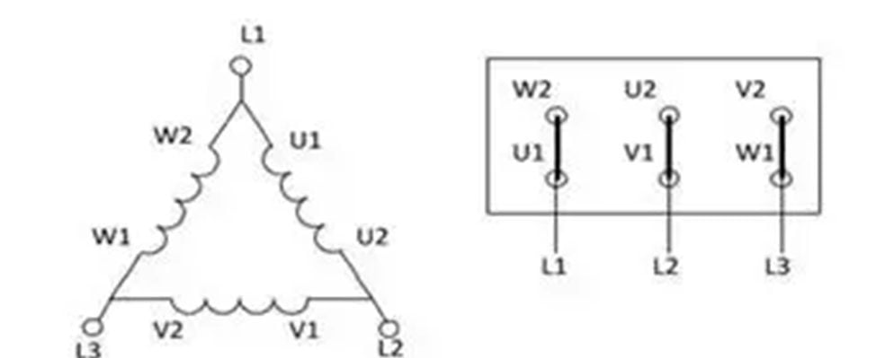 Important Notes:
- You must ensure that the terminals are connected correctly, otherwise it may cause an increase in the current value and the motor will not be able to reach its normal speed and burn out.
- When you notice that there are voltage values like the following: 220V/380V, this means that the motor operates as Star at a voltage of 380V and Delta operates at a voltage of 220V.
Delta circuit analysis
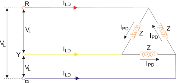
Delta circuit characteristics
- The line voltage (VL) is equal to the phase voltage Vph .
- You can find the line current using the following equation:

- The phase current is equal to the line current dividing the root of three, or using Ohm’s law as shown in the following law:

The difference between a star circuit and a delta circuit
1- Star Circle:
- The line current passing through the circuit is equal to the phase current, because the current passes in one direction.
- There is a return line in the circuit, which is the neutral line (N).
- The line voltage is equal to the phase voltage times the root of three
2- Delta circle:
- The line voltage (VL) is equal to the phase voltage Vph
- The line current is distributed over the two coils, so the phase current is equal to the line current divided by the root of three.
- There is no return line in the circuit, which is the neutral line (N).
We have reached the end of the article on the difference between a star circuit and a delta circuit, which is explained with an explanation and illustrative pictures of how to connect a star circuit and a delta circuit.
Connecting the star delta circuit
Connecting the Star Delta Circuit, 3-phase electric motors are used in various industrial fields, and we know that every large 3-phase motor needs a dedicated circuit to reduce the value of the starting current, and this circuit is called the Star Delta circuit.
We use the Star circuit only to reduce the value of the motor current at the moment of startup, while the Delta circuit we use to run the motor permanently until the motor is disconnected from the electrical source.
Information about connecting the Star Delta circuit
First, you must know the external connection points of the 3-phase electric motor, as the motor contains six terminals that connect either in the form of a star or a delta.
Internally, the engine contains three coils, each coil having a start end and an end end. The beginning ends are symbolized as follows: (U1, V1, W1), and the ends are symbolized as follows: (U2, V2, W2).
In the case of delta, the 3-phase electricity source is connected to the beginnings or ends. While a star circuit connects the ends of the ends together with a metal conductor and connects the current source to the beginnings, and it is possible to do the opposite, i.e. to bring the beginnings together and connect the current source to the ends.
Why is the star delta circuit connected?
Because the Star circuit reduces the starting current at the moment of operation only, while the Delta circuit gives the engine full speed so that the engine runs normally throughout the continuous operation time.
Important note:
3-phase motor manufacturers set the voltage and current of the star circuit and the delta circuit, and the most popular voltage values are 380V/660V or 220V/380V, and the delta voltage is always less than the star voltage, while the star current is less than the delta current.
How to choose contactors and overloads
- The main contactor K1 and the delta contactor K3 are chosen based on the intensity of the motor current and it operates on a star connection, because the current in the delta case is distributed among the two contactors (K3, K1).
- The K2 star contactor is selected based on the motor current and operates on a delta 3 division (delta/3 current).
- As for the overload, it can be connected directly to the power source after the fuses so that it is calibrated for delta current.
- It can also be connected below the main contactor K1 so that it is calibrated to star current.
Pieces used in connecting the Star Delta circuit
- Three contactors (Star Contactor, Delta Contactor, and Main Contactor).
- overload
- Three fuses. Main.
- 3 phase electric motor.
- On-delay timer.
- Auxiliary points for contactors (open and closed points).
- On switch and disconnect switch.
Star delta circuit wiring diagram
Explanation of connecting the Star Delta circuit
When the power source is connected to 3 phases in the power and control circuit, the circuit does not start the engine immediately unless the start switch is pressed by hand.
Then the current in the control circuit passes through the overload contacts, the stop switch and the start switch to feed the timer K1T.
Simultaneously with the timer supply, current also passes to the star contactor coil K2 through the closed timer contact and the closed delta contactor K3.
The current also passes through the open point K2 to feed the main contactor coil K1, creating a connection between the open point K1 connected in parallel with point K2, thus the main contact points of contactor K1 and contactor delta are connected.
After the timer has finished counting, it changes its contact points, so the circuit is converted from star to delta by disconnecting the current from the star contactor coil K2 and connecting the delta contactor K3 while the contactor K1 remains connected without any change in its contact points. Connected without any change in its contact points.
In the event of any malfunction, the overload disconnects the main and auxiliary contacts between the power and control circuits to stop the motor from rotating.
When will the Star Delta engine arrive?
When will the Star Delta engine arrive? An important question that some people ask about the Star Delta circuit. As we know, not all motors must be connected to Star Delta, but only 3-phase motors.
We also find a data card glued to the surface of the motor with all the required data written on it, which concerns us in knowing how to connect it in terms of star voltage and current, as well as delta voltage and current. We have dedicated a special topic for you to this question, and what you should know about the star delta circuit.
Connecting the star delta motor
Before you start connecting the circuit, you must first learn about the external connection of the motor. Any 3-phase, single-speed motor has a beginning and an end for each phase, and the six terminals are symbolized by internationally recognized symbols:
| # | beginning | end |
|---|---|---|
| First win | U1 | U2 |
| The second victory | V1 | V2 |
| The third victory | W1 | W2 |
Any 3-phase electric motor with one speed can operate on two different voltages (star/delta) with the difference between them being the root of three, such as: 380V/660V.
If the motor operates at a lower or higher voltage, provided that the external relay is connected correctly, the motor will operate at its full capacity and at the same speed in both cases.
When will the Star Delta engine arrive?
The process of connecting any 3-phase Star Delta electric motor is done based on the voltage and current recorded on it, and as we know, connecting it to Delta operates at a lower voltage and in return draws a higher current. While connecting it to a curtain works on a higher voltage and draws a lower current.
That is, if it is written on the surface of the motor 220V/380V – 1.7A/3A and the voltage source that will be connected to this motor is 220V, it must be connected in delta, but if it is connected to Star and the value of the source is the same, the motor will work at approximately half its capacity, and this will cause the motor to burn when it is loaded. Full load.
The bottom line:
In short, different voltage values are usually written on the motor, such as: 380V/660V or 220V/380V. This means that the lower value communicates delta and the higher value communicates star. Therefore, make sure that the supply voltage value matches the lower voltage value (the motor voltage while it is running delta). ).
Electrical components Circuit
Electrical circuit components
We are pleased that you visit our social media pages, where we publish exclusive offers on our website.
Our Facebook page Here.
Our Twitter account Here.







Leave a Reply
You must be logged in to post a comment.