Calculation of Suitable electrical cable, taking into account the distance 1
Calculation of Suitable electrical cable, taking into account the distance
 Calculation of Suitable electrical cable, taking into account the distance
Calculation of Suitable electrical cable taking into account the distance. Electrical cables are considered one of the important elements of electrical designs that are not devoid of any electrical network. There are steps and factors that affect the selection of the appropriate electrical cable section. Therefore, let us learn how to calculate the electrical cable, taking into account the distance, step by step.
Calculation of Suitable electrical cable, taking into account the distance
The relationship of the electrical circuit breakers to the cable clip
At the beginning of the initial design, the capacity of the electrical circuit breaker suitable for the electrical load is chosen, then the cable section, and not vice versa, with the aim of protecting the cable by means of the circuit breaker. This is not considered the final design unless the selection is confirmed by three main and important tests, namely:
- Thermal endurance of the cable by studying the air temperature, laying conditions and other procedures that must be followed in order for the cable to bear these requirements.
- The extent of the voltage drop to ensure that the value at the end of the cable does not exceed the permissible limits.
- Withstand the cable and the electric cutter for the maximum short current expected to pass through the cable and the electric cutter.
Important note: These tests are applied to the main cables and some special cases if the distance between the distribution panel and the load is very long only, and not the sub-lighting circuits or small loads close together such as the loads in the house.
Electric circuit breakers and electric cables
Factors affecting the selection of cable section
Factors affecting the selection of the main cable section designed for long distances are as follows:
- Correction factors for loading cables: including the effect of temperature, depth of burial, the effect of specific heat of the soil, and adjacent cables above or under the carriers.
- voltage drop rate.
- Maximum expected short-circuit current: The maximum short-circuit current to be tolerated by the circuit breaker and cable and the disconnection time must be coordinated.
The maximum value that the cable can withstand during shorting can be obtained in one of the following ways:
- Through special schedules provided by cable companies.
- Using the curves of the cable companies.
- Using approximate calculations (it varies from company to company).
Important note: We mention these steps that every technician and engineer must abide by and use the cable catalogs that you use in electrical designs, because the values, laws and calculations that companies put into the catalog differ from one company to another.
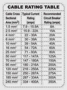
 The cable (wire) suitable for the electrical circuit breaker
| cable clip (wire) | Electric breaker capacity |
| 1.5 mm² | 10 amps |
| 2.5 mm² | 16 amps |
| 4 square mm | 20 amps |
| 6 square mm | 25 amps or 32 amps |
| 10 square mm | 32 amps or 40 amps |
| 16 square mm | 40 amps |
| 25 square mm | 63 amps |
| 35 mm | 80 amps |
| 50 square mm | 100 amps |
| 70 square mm | 125 amps or 160 amps |
The cable (wire) suitable for the electrical circuit breaker
The maximum current that a section of electric cable can withstand
Here is an approximate table taught to electrical students showing the value of the maximum current that a section of electric cable can withstand.
| cable clip | maximum current it can handle |
| 1.5 mm² | 18 amps |
| 2.5 mm² | 21 amps |
| 4 square mm | 27 amps |
| 6 square mm | 35 amps |
| 10 square mm | 48 amps |
| 16 square mm | 65 amps |
| 25 square mm | 88 amps |
| 35 mm | 110 amps |
| 50 square mm | 140 amps |
| 70 square mm | 175 amps |
| 95 square mm | 215 amps |
| 120 square mm | 255 amps |
| 185 sq. mm | 338 amps |
The maximum current that a section of electric cable can withstand
Note: These values are approximate and vary by cable configuration and manufacturer.
We note that the values in the above table are initially calculated on the basis of a copper conductor with a length not exceeding 40 meters without relying on the length of the cable, the type of conductor (copper – aluminum – a mixture between the two types) and the location of the cable (in the air – under the ground – inside a pipe – adjacent with another cable), voltage drop, short circuit current, and temperature correction coefficient.
All of the things I mentioned affect the selection of the appropriate cable section and the amount of influence is increased.
Steps for Calculation of Suitable electrical cable, taking into account the distance
Simply, without going into the details of voltage drop and distances, there are three main steps that can be used for home wiring:
- First: calculate the current of the electrical device
Electric current (I) = electrical device power (P) ÷ (source voltage (V) x power factor (PF))
whereas:
Ampere (A)
Volt (V)
The value of the power factor is between 0.8 and 1, depending on what is written on the device.
- Second: Calculating the current capacity of the electric circuit breaker:
The current capacity of the electrical circuit breaker = the current of the electrical device x a safety coefficient ratio (1.25)
Then we choose the closest breaker capacity available in the market so that the capacity is greater than the value that appeared in the output.
- Third: Calculating the area of the electric cable section
Electric cable section = breaker current capacity x safety coefficient ratio (1.2)
Then we choose a cable section that can withstand a current higher than the value that appeared in the result, and this is done by relying on the data sheet of the cable and searching for the current capacity table that each cable section can bear.
Important note: These calculations are suitable for cables used in home wiring and small buildings.
And for short distances, as the large distances need additional calculations such as: voltage drop percentage, short current, and correction coefficients.
Calculation of Suitable electrical cable, taking into account the distance
An electric load with a capacity of 2000 watts and works on a voltage of 220 volts, knowing that the power factor of this device is 0.9.
Calculate the current of the load, the capacity of the suitable breaker, and the area of cable section suitable for this load.
the solution:
Electric current (I) = electrical device power (P) ÷ (source voltage (V) x power factor (PF))
= 2000 ÷ (220 × 0.9)
= 2000 ÷ 198
Load current = 10 amps
The current capacity of the electrical circuit breaker = the current of the electrical device x a safety coefficient ratio (1.25)
= 10 × 1.25
= 12.6 amps
The closest circuit breaker current available on the market is 16A.
Electric cable section = breaker current capacity x safety coefficient ratio (1.2)
= 16 x 1.2 = 19.2 amps
The closest cable cross section available on the market is 2.5mm square that can withstand a current of 21A.
Calculation of Suitable electrical cable, taking into account the distance
Calculation of Suitable electrical cable, taking into account the distance
Choosing the appropriate cable for long distances is a very important issue that some people may ignore in calculations by limiting themselves to determining the load current and the circuit breaker without taking into account the length of the distance between the load and the source, and the voltage drop rate.
In this article, we will learn about the best methods through which we can determine the area of the cable section required for the load, based on the Swedish Cable Catalog.
 Steps required to select the appropriate cable section
The appropriate cable cross-sectional area for long distances is chosen according to:
- load current.
- The voltage loss is less than 5%.
- Palace current and separation time.
At first you calculate the load current using the following formula:
Current (3 phase) = (kilowatts x 1000) ÷ (1.73 x voltage x power factor)
After that, you choose the appropriate breaker by adding a safety coefficient of (25%) above the value of the load current. Finally, the most important stage comes, which is choosing the appropriate cable section area based on the correction coefficient table, the voltage drop percentage, the short circuit current, and the disconnection time.
- Correction coefficient when laying the cable in the ground with a depth of 80 cm and a temperature of 70 degrees Celsius (PVC=0.76/ XLPE=0.85).
- Correction factor when the cable is laid in air and at a temperature of 70 degrees Celsius (PVC = 0.82 / XLPE = 0.89).
- Determine the voltage drop percentage from the cable schedule.
- Short circuit current and disconnection time: Each electrical circuit breaker bears a maximum short circuit current value that you find written on the circuit breaker in units of kiloampere. Also, the circuit breaker has a disconnect time, so it is necessary to choose the appropriate cable so that it can withstand the maximum short circuit current, and that it is also able to withstand Separation time.
How to choose the right cable for long distances
Practical example:
Electric motor has the following specifications
- Horse power = 50 horsepower.
- Feeding voltage = 380 volts.
- Power factor = 0.8
- The distance between the load and the source = 150 meters.
Choose the required cable to carry the electric motor?
First: calculate the load current
Power in kilowatts = horsepower x 0.746
= 50 x 0.746 = 37.3 kilowatts
Current (3 phase) = (kilowatts x 1000) ÷ (1.73 x voltage x power factor)
= (37.3 × 1000) ÷ (1.73 × 380 × 0.8)
= 37300 ÷ 525.9
= 70.9 amps
Second: Calculating the appropriate cutter capacity
Suitable breaker capacity = motor current x 1.25
= 70.9 × 1.25
= 88.6 amps
The closest breaker available is 100 amp.
Third: Choosing the area of the cable section
Suitable cable = breaker current ÷ correction factor (PVC cable laid in air)
= 100 ÷ 0.82
= 122 amps
The closest cross-sectional area of the cutter is 35 mm2
Some may be satisfied at this point, but there are some steps that affect increasing the required cable section area.
Fourth: Calculating the Voltage Loss (VD)
It must be taken into account that the voltage drop is less than 5% as follows: (0.05 x 380 volts = 19 volts), therefore the maximum permissible voltage drop value is only 19 volts.
From the table, we notice that the value of the voltage drop (mv/ Amp / meter) at the intersection of the cable cross-sectional area with the PVC copper conductor column is 0.726, so the voltage drop will be:
Voltage drop (VD) = 0.726 x 122 x 150
= 13.2 volts
So the design is in order until this moment, because the value is less than the maximum allowable voltage drop value of 19 volts.
Fifth: The extent to which the cable can withstand minor current
If the maximum short-circuit current that the breaker can withstand in 0.5 seconds is 10 kA, then the cross-sectional area of the new cable is 70 mm2.
So the electric motor needs the following:
- Electric breaker 100 amp / 10 kilo amp
- Cable with a sectional area of (4×70)+35
Calculation of the section of solar cables
Calculating the section of solar energy cables, the cables connect all components of the solar system, so they are the backbone of the solar energy system.
It is necessary to study the issue of solar energy cables carefully and to rely on the correct electrical laws in the calculation process in order to make it easier for you to determine the appropriate electrical cable diameter.
We should not fail to point out that the correct design of the solar system, especially the calculation of the section of the solar energy cables, is what determines the quality of proper work. Therefore, we must be extremely careful when choosing the diameter of the DC electric cable.
Connecting solar energy cables
We need cables dedicated to the solar system in order to connect the current between the components in the system, and we can find them in five places as follows:
- between the solar panels and the charger.
- between the charger and the battery.
- between the battery and the inverter.
- between the inverter and the AC loads.
- between the charger and the DC loads.
However, cables are an important source of electrical losses due to voltage drop and thermal losses. Therefore, we have to design these cables so as not to exceed the standards shown in the following table:
| cable path between | maximum voltage drop |
|---|---|
| Solar panels and charging regulator | 3% |
| Charge and battery regulator | 1% |
| battery and inverter | 1% |
| Inverter and alternating current loads | 3% |
| Charge regulator and DC loads | 3% |
Solar cable section calculation rules
Typically, split power systems operate on low voltages and high currents; We need to calculate the section of cables that are able to withstand these high currents while maintaining the levels of voltage drop referred to in the previous table.
The cross section of solar power cables can be calculated using the following equations:
DC Cable Section = (1.4 x 2 x L x I x P) ÷ (V x Voltage Drop %).
AC cable section (1 phase) = (1.4 x L x I x P) ÷ (V x voltage drop %).
whereas:
| 1.4 | Safety coefficient |
| L | cable length |
| I | The intensity of the flowing current |
| P | Specific resistance (for copper 0.01724) |
| V | voltage difference |
Calculate the cable section between the panels and the charging regulator
Calculation steps:
- First of all, you have to take into account that the voltage drop should not exceed 3%.
- Measure the length of cable between the panels and the charging regulator.
- Determine the total voltage of the panels when connected in series (ie in the form of strings).
- Determine the total current passing in this path, by determining the number of strings connected in parallel and multiplying it by the current of one plate for each string
- Using the DC cable section calculation law.
Determine the appropriate cable section between the panels and the regulator
Four solar panels were connected as follows: each two panels are connected in series to form a string, and the strings are connected in parallel together. Note that the distance between the panels and the charging regulator is 20 meters, the specific resistance of copper is 0.01724, and the maximum allowable drop in voltage is 3%.
- Calculate the total voltage and total current leaving the panels.
- Calculate the appropriate cable section between the panels and the charging regulator.
Solar panel data
| plate effort when working | 34.2 volts |
| Slab short circuit current (Isc) | 12.28 amps |
the solution:
Step One: Calculating the Total Panel Voltage:
Total solar panel voltage (Vmp) = single panel voltage x number of panels connected in series
= 34.2 volts x 2
= 68.4 volts
Step two: Calculate the total panel current
Total Panel Current (Isc) = Current per panel x Number of strings connected in parallel
= 12.28 × 2
= 24.56 amps
Step Three: Calculate the appropriate cable section
DC Cable Section = (1.4 x 2 x L x I x P) ÷ (V x Voltage Drop %).
= (1.4 × 2 × 20 × 24.56 × 0.01724) ÷ (68.4 × 0.03)
= 23.7 ÷ 2
= 11.85 amps
The closest cable cross-sectional area available on the market is 16mm2
Calculate the cable section between the batteries and the charging regulator
In this path, we are allowed to drop a voltage that does not exceed 1%, and the current entering the charging regulator is the same as the exit from it for the battery. The cable section space between the battery and charge regulator is usually thicker in low voltage systems.
Determine the appropriate cable section between the batteries and the regulator
We have one battery with electrical specifications (12V/100Ah), the copper cable distance between the regulator and the battery is 2 meters, and the permissible voltage drop is 1%. Calculate the appropriate cable cross-sectional area if the regulator current is 40A?
the solution:
DC Cable Section = (1.4 x 2 x L x I x P) ÷ (V x Voltage Drop %).
= (1.4 × 2 × 1 × 40 × 0.01724) ÷ (12 × 0.01)
= 1.93 ÷ 0.12
= 16 mm2
We choose 16mm2 cable sectional area, and you can also choose 25mm2 cable sectional area.
Calculating the cable section between the battery and the inverter
The power of the inverter is calculated based on the power of the total electrical loads in watts, and the cable section between the battery and the inverter is calculated by dividing the power of the inverter by its input voltage.
- Example of selecting the appropriate cable segment between the battery and the inverter
If we have loads of 500 watts and the inverter operates on an input voltage of 24V/DC, the distance between the inverter and the battery is 3 meters, and the permissible voltage drop does not exceed 1%, calculate the area of the appropriate cable section?
the solution:
Load current = (Total load power x 1.25) ÷ Inverter input voltage
= (500 × 1.25) ÷ 24
= 625 ÷ 24
= 26 amps
Since the current is continuous, we use the following law:
DC Cable Section = (1.4 x 2 x L x I x P) ÷ (V x Voltage Drop %).
= (1.4 × 2 × 3 × 26 × 0.01724) ÷ (24 × 0.01)
= 3.76 ÷ 0.24
= 15.68
The closest available cable cross-sectional area is 16 mm2
However, it is always preferable to calculate the area of the cable section between the batteries and the inverter based on the capacity of the inverter and not the loads in order to ensure that the cable carries the maximum current that can pass through it from the inverter, and also because we do not guarantee that someone will add an additional load above the load that we estimated for the current passing through.
The same thing applies to calculating the cross-sectional area of the cables between the inverter, the alternating current loads, the charging regulator, and the DC loads, and be sure to use the correct law in the calculation process, meaning if the cable to be calculated is the cross-sectional area between the inverter and the alternating current loads, use the alternating current law, and so on.
[embeddoc url=”https://www.gahzly.com/wp-content/uploads/2022/06/electric-cable-with-distance-1.pdf” download=”none” viewer=”google” “]
Calculate the appropriate electrical cable section

We are pleased to have you visit our pages on social networking sites, where we publish exclusive offers on our website.
Our Facebook page here .
Our Twitter account here .


Leave a Reply
You must be logged in to post a comment.