Amplifier circuit using
Amplifier circuit using IC555 Amplifier circuit using IC555. We present to you a simple and easy amplifier circuit that does not require a lot of time when assembling it. It is a useful circuit for amplifying sound and does not require a…

Amplifier circuit using
IC555
Amplifier circuit using IC555. We present to you a simple and easy amplifier circuit that does not require a lot of time when assembling it. It is a useful circuit for amplifying sound and does not require a lot of electronic parts. How can a speaker circuit be connected using IC555? Follow us to learn about the circuit diagram. And how to deliver it.
Describe the amplifier circuit using
IC555
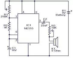 The amplifier circuit is useful as a small and simple project for beginners and specialists in the field of electronics. Although it is not very practical, it is cheap and does not require a lot of electronic parts, and even non-specialized people have the ability to connect the circuit.
The amplifier circuit is designed based on the IC555 timer circuit, some resistors, capacitors, a microphone, an 8 ohm speaker, and finally a 9 volt DC power supply.
Electronic parts used in the circuit
| Parts used | the number | the value | Quantity |
| IC555 | U1 | DIP8 | 1 |
| Fixed resistance | R1/R2/R3/R4/R5/R6 | 47k/680k/100k/470k/1k/10k | 6 |
| Polarized capacitors | C2/C3/C4 | 1nF/10µF/10µF | 3 |
| Polarized capacitor | C1 | 100nF | 1 |
| Mike | MIC | – | 1 |
| Constant voltage source | VCC | 9V | 1 |
| Loudspeaker | – | 8 ohm | 1 |
Amplifier circuit diagram using
IC555
 Explanation of amplifier circuit using
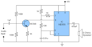
 IC555
IC555
After completing the correct connection of the circuit and feeding it with a 9V source, you can emit a sound near the microphone. The circuit then converts the emitted sound into an electrical signal, organizes it, and amplifies it through the rest of the circuit components, such as the IC555 timer, capacitors, and transistors.
You can also connect a 3.5mm headphone connector instead of the microphone, but you must remove the resistor R1 from the circuit as well with the microphone, and connect the left or right headphone end with the capacitor C1 end and the negative end of the headphone connector with the negative of the circuit.

We are pleased that you visit our social media pages, where we publish exclusive offers on our website.
Our Facebook page Here.
Our Twitter account Here.