What is the difference between contactor and relay?

sell online December 28, 2023 20 min read

What is the difference between contactor and relay?

What is the difference between contactor and relay? The difference between contactor and relay: understanding the basics Contactor and Relay are considered an essential part of electrical systems Each of them plays a vital role in controlling the flow of electrical current.…
What is the difference between contactor and relay?
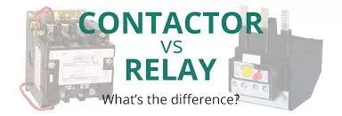
What is the difference between contactor and relay?

What is the difference between contactor and relay?

The difference between contactor and relay: understanding the basics

Contactor and Relay are considered an essential part of electrical systems Each of them plays a vital role in controlling the flow of electrical current. Although they share their main purpose, they differ in their design and basic functions.

Relay:

A relay is a device that converts electrical current or voltage. The relay consists of a coil and a base containing several electrodes. When current is passed through the coil, a magnetic field is generated that causes the poles at the base to open or close. A relay is generally used to control remote control circuits, as it can switch between different electrical circuits with a small electrical signal.

Contactor:

In contrast, contactors are used to control large electrical currents. The contactor consists of a group of connections and separations that can withstand high currents. The contactor can be operated by a low-voltage electrical signal that is used to control large wattage circuits, making it ideal for use in industrial applications and large electrical systems.

In short, it can be said that a relay is a device that operates on the principle of switching by an electrical signal, while a contactor is used to control large electrical force currents. In this article, we will highlight the main differences between them and the importance of using each in their respective contexts.
What is the difference between contactor and relay?

Contactor:

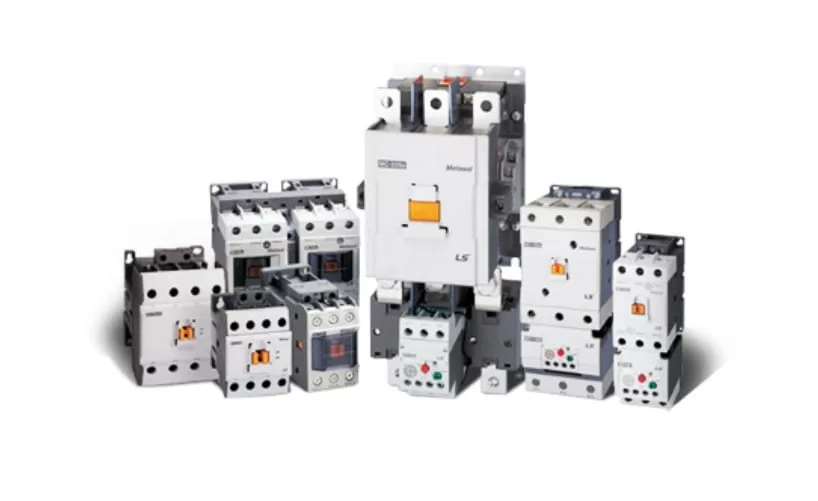
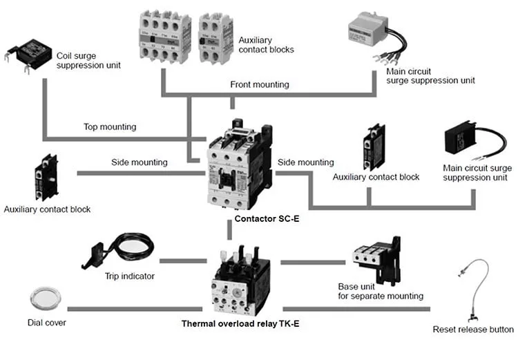
The contactor is an electrical device of great importance in the field of electrical engineering, as it is used to effectively turn on or off electrical circuits. The contactor belongs to a special class of electrical relay devices.

However, the main difference between a relay and a contactor is that a contactor is used in applications that require the ability to handle high currents, while a relay is used in low-current applications.

The contactor is easy to install on site and compact in size, making it a suitable choice for a variety of applications. The advantage of these electrical devices is the presence of multiple contacts, as these contacts are usually open in most cases, which allows operating power to be provided to the load when the contactor coil is activated.

Contactors are widely used in the control of electric motors, as they provide the ability to switch large electrical power circuits efficiently. Contactor sizes range from hand-held dimensions to large sizes suitable for large industrial applications, reflecting their flexibility in integration with various environments and requirements.

In general, contactors are essential for controlling large wattage currents, as they are capable of handling currents of thousands of amperes and high power of 100 kW or more. In addition, contactors are an effective solution for controlling the generation of electrical arcs that occur during outages, making them a reliable solution for large and strong load current applications.

Contactor components: a deeper understanding

What is the difference between contactor and relay?

Contactors are complex and effective electrical control devices, consisting of several main components that work in harmony to achieve the desired performance. Here is a more detailed explanation of these components:

  1. Coil or electromagnet:
    • The coil, or electromagnet, is the heart of the contactor, providing the driving force needed to close the contacts.
    • The coil or electromagnet is placed inside a protected enclosure to ensure its safety and achieve electrical insulation.
  2. Enclosure:
    • The enclosure provides protection and isolation for connectors and contacts.
    • Enclosures are made of insulating materials such as polycarbonate, polyester, nylon 6, Bakelite, and thermoplastic.
    • The protective cover protects the contactor from bad environmental conditions and potential hazards such as explosions, dust and oils.
  3. Contacts:
    • Contacts are a vital element in transmitting electrical current.
    • It bears the current load of the contactor and ensures efficient and reliable conduction.
    • They come in different types such as contact springs, auxiliary contacts and power contacts, with each type playing a specific role in the overall performance of the contactor.

Combined, these components integrate to achieve outstanding contactor performance, as it can handle high currents and withstand various environmental conditions efficiently. The meticulous design and quality of the components combined with a deep understanding of various applications reflect the strength and effectiveness of these electrical devices in many areas.

A contactor is an electrical device that facilitates the efficient turning on and off of electrical circuits. The work of the contactor is based on the interaction between the electrical coil and the contacts, and it works according to the following mechanism in more detail:

  1. Coil or electromagnet:
    • The file plays a vital role in the work of the contactor. When electrical current is applied to the coil, a magnetic field is created around it.
    • This field causes a moving part of the contactor, such as the conductor core, to attract, closing the circuit.
  2. Contacts:
    • The contacts are moved by the rotor and the magnetic field. When the rotor is moved, the contacts are opened or closed.
    • The common contact is normally open (NO), which is open when no current is passing. When the coil is energized, the contact closes to allow current to flow.
  3. Current and load:
    • After the coil is excited and the contacts are closed, electric current flows through the contactor to an electrical load, such as an electric motor.
    • When the current is removed or disconnected, the coil is turned off, causing the contacts to open and interrupting current to the load.

Briefly, a contactor is energized by an electrical coil using current, causing the contacts to move and open or close the electrical circuit. This design provides an effective means of controlling electrical loads on and off efficiently.

Types of contactors:

  • Knife blade switch was a technology used in early times to control electric motors. This technique was based on a metal strip falling onto the contact, and it had a lever to pull the switch down or push it up.

    In that period, one had to manually adjust the knife blade switch by standing next to it. However, there was a problem with this method in that the contacts wore out quickly. It was difficult to open and close the switch quickly enough to avoid corrosion.

    This method quickly damaged the contacts, especially for soft brass switches, leaving them vulnerable to moisture and dirt. As motors increased in size over time, increasingly larger currents were required to operate them, increasing the risk of corrosion and creating safety concerns.

    Despite attempts at mechanical improvement, serious operating problems and short service life of the contacts meant that the knife blade switch was not fully developed.


  • The means of controlling the operation of electric motors have evolved over time, as a result of the development of technology and the increasing need for safer and more effective methods. One of these developments was the introduction of the hand controller, which brought new features and solutions to the challenges faced in using knife blade switches.

    Among the main features of the manual controller:

    1. Safe for work:
      • The hand controller is designed to be safe to use, reducing the risk of accidents.
    2. Encapsulated unit:
      • The controller is properly packaged, which protects it and makes it ready to work in different conditions without getting damaged.
    3. Physically smaller size:
      • Thanks to technical improvements, hand controllers have become smaller, making them easier to install in tight spaces.
    4. Dual contacts:
      • The single contacts were replaced with double break contacts, allowing the circuit to be open in two places at the same time, increasing the carrying capacity for larger currents.
    5. Operation:
      • The hand controller is not operated remotely, but is connected directly to the actual unit. When activated, they transmit electricity to the load, making it easier to control the switching on and off of loads.

    In general, manual controllers have improved the controls of electric motors and increased safety and efficiency in use. This development contributed to enhancing the performance of electrical systems and improving the operating experience.


  • Magnetic contactors are an advanced technology in the field of electrical control and are widely used in industrial control applications. Here are some key points about this technique:

    1. Operation without human intervention:
      • Magnetic contactors do not require human intervention for operation; Instead, they rely on electromechanical action to open and close the circuit. This increases safety and reduces the risk of manual operation.
    2. remote control:
      • Magnetic contactors can be operated remotely, making it easier to control electrical circuits in industrial environments.
    3. Small control current consumption:
      • Magnetic contactors require small amounts of control current to open or close the circuit, which contributes to energy efficiency.
    4. Common use in industrial control:
      • Magnetic contactors are the main types of contactors used in industrial control applications, providing efficient control of electrical circuits.
    5. Average life expectancy:
      • The life expectancy of magnetic contactors is one challenge, as it relates to wear resulting from frequent opening and closing operations. This average is affected by the arc extinction speed and maintenance efficiency.
    6. Electric arc control:
      • Arc control techniques improve the life of contacts and reduce the impact of corrosion, so their life span can be increased.

    All in all, magnetic contactors are an effective technical solution for controlling electrical circuits, and their performance is constantly improved by advanced control technologies and innovations in industrial contactor design.


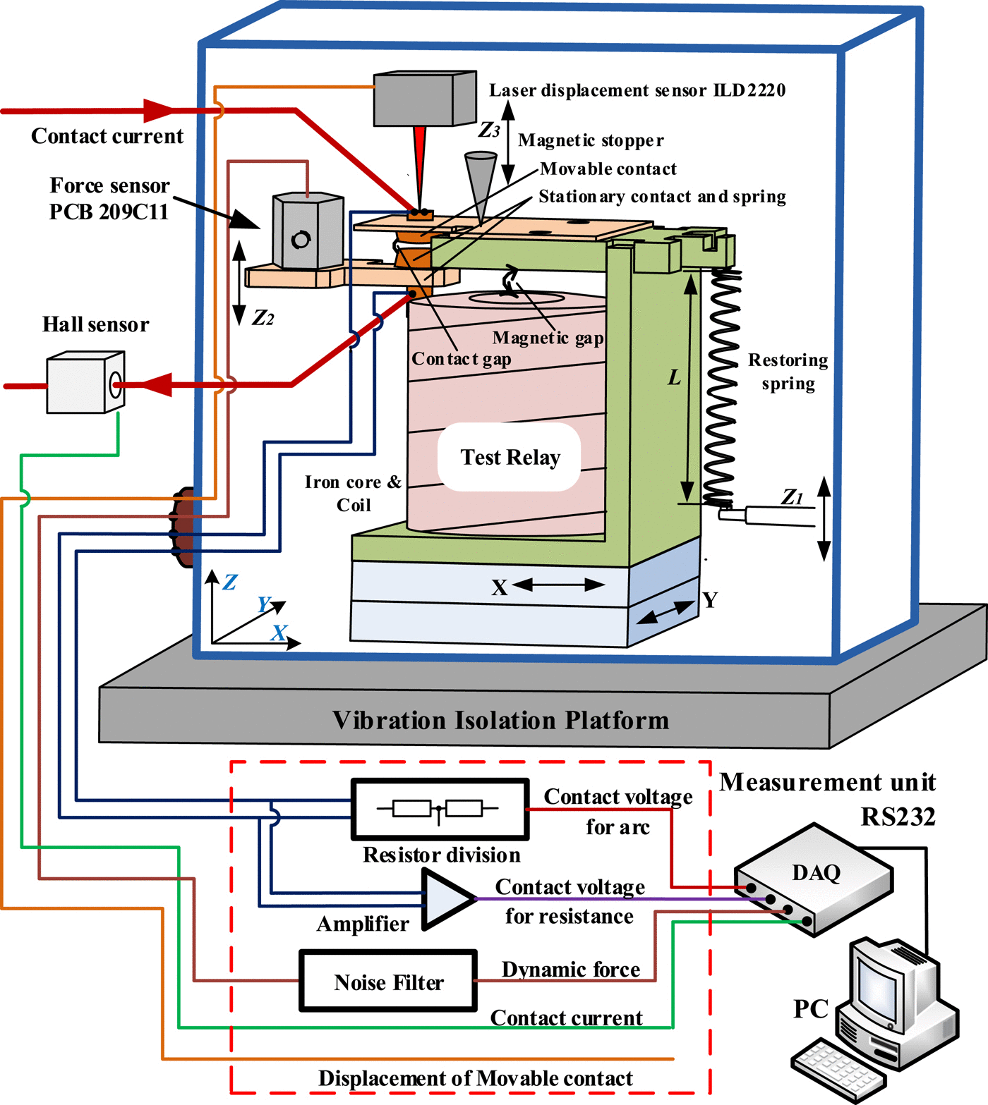
A contactor is a complex electrical device consisting of several main parts. Here’s an explanation of some of the main parts and their functions:

  1. A fixed iron core and a movable one:
    • The fixed and moving iron core forms the main part that moves by the electric coil and opens or closes the electric current circuit.
  2. Copper coil:
    • It wraps around the iron core and is responsible for creating a magnetic field when electric current is passed. This field affects the moving core to open or close the circuit.
  3. Return spring:
    • The spring helps in returning the moving core to its original position once the electrical coil is turned off and the power is cut off.
  4. Fixed and moving contacts:
    • These contacts are part of the electrical circuit, and when the moving core is moved the contacts close to allow electrical current to flow.
  5. Portfolio:
    • The case provides the necessary protection for the internal parts of the contactor and protects against external environmental conditions.

These key parts have complex interactions and cooperation to achieve effective and safe opening or closing of an electrical circuit.

What is the difference between contactor and relay?

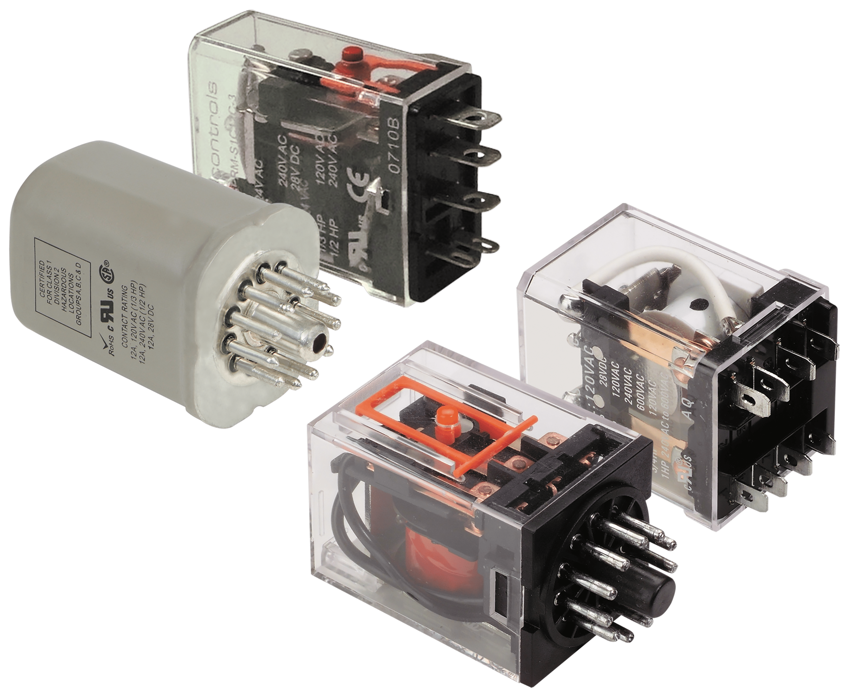
The relay is a device similar in internal structure to a contactor, as it consists of the following elements:

  1. the heart:
    • The core is the main part of the relay assembly, and can be iron or a similar material. The heart is affected by the magnetic field that arises when the coil is activated.
  2. File:
    • The coil consists of a copper wire wrapped around the core. When electric current is passed through the coil, it creates a magnetic field that affects the core.
  3. Moving arm:
    • The moving arm is connected to the heart, and is affected by the magnetic forces of the heart. The lever opens or closes the contacts based on the condition of the coil.
  4. Fixed and moving contacts:
    • These contacts form part of the electrical circuit and control the flow of current. When the moving arm is moved, the contacts close or open to pass or cut off current.
  5. Return spring:
    • The spring is used as a means of returning the movable arm to its original position once the coil is turned off and the power is cut off.

These parts cooperate in an integrated manner to achieve the process of opening or closing the electrical circuit in the relay effectively and under the direct influence of the magnetic field created when the coil is activated.

Relay:

The relay is an advanced and flexible device that can be separated from its base. This plug allows the terminals of the relay to be connected to the base according to the numbers or symbols written on it.

The relay can be easily changed or replaced when needed, as it can be removed from the base and another relay of the same model can be connected quickly and easily.

Although the relay is usually used in control circuits rather than power circuits, it plays a crucial role in controlling the connection or disconnection of current to the contactor coil, and sends control signals to other elements.

The relay has a low current consumption and its contacts are designed to handle up to 10A, making it suitable for a wide range of applications in complex electrical systems.

What is the difference between contactor and relay?

Relays are devices that open and close circuits electromechanically or electronically, and are used to control the turning on and off of electrical circuits. Here’s how relays generally work:

  1. Stage installation:
    • Relays consist of a relay device containing contacts and an electrical coil.
    • The coil has a crucial role in turning on the phase, as it is energized when electrical current is applied to it.
  2. Contacts:
    • Relays have moving and fixed contacts.
    • In the coil de-energized mode, the contacts are normally open or normally closed, depending on the phase type.
  3. Control process:
    • When the coil is energized, a magnetic field is generated around it.
    • This causes the moving contacts to move, closing or opening the electrical circuit to which they are connected.
  4. Types of relays:
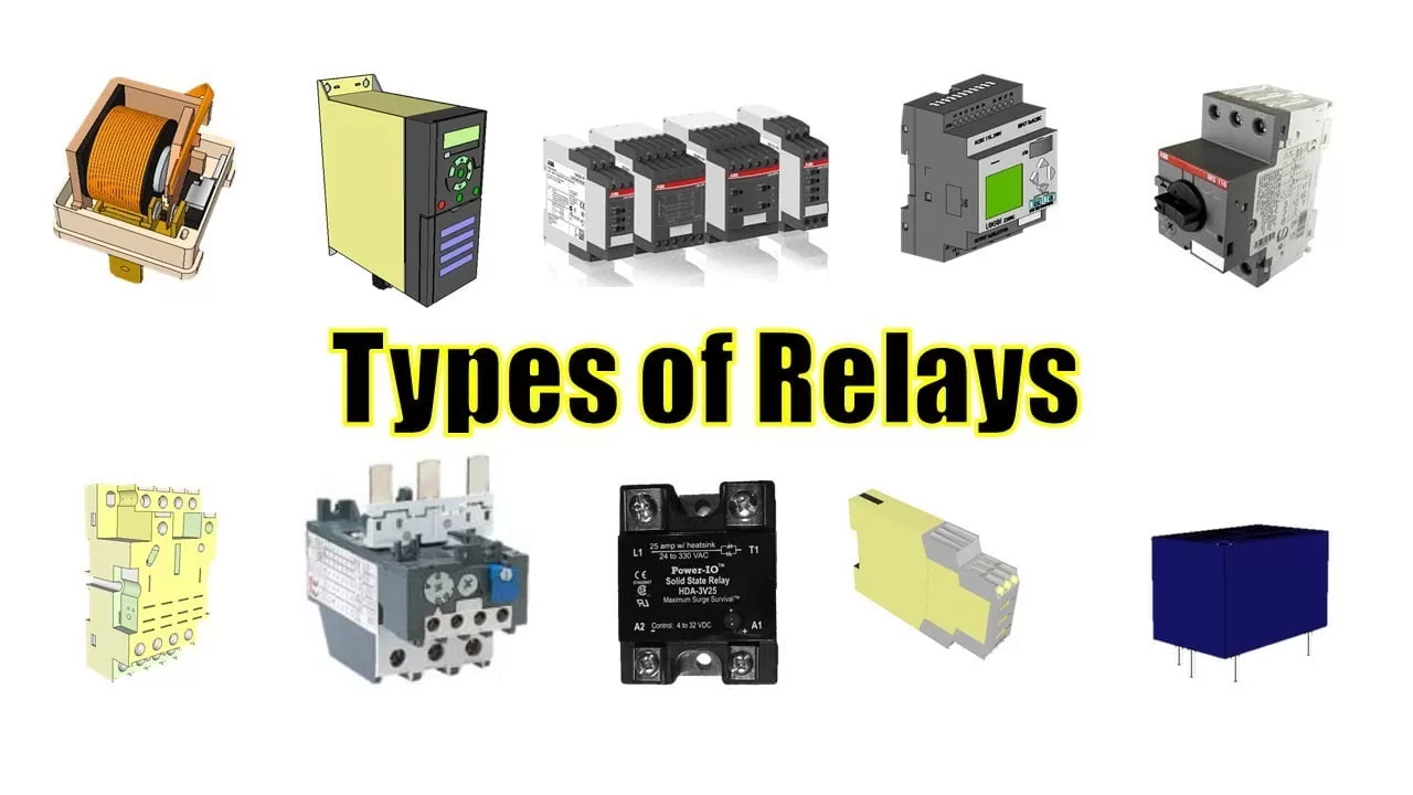
    • There are different types of relays, including electromechanical relays and solid-state relays.
    • Electromechanical relays use mechanical components in which the contacts move.
    • Solid state relays use electronics to achieve circuit control without a moving mechanical part.
  5. Applications:
    • Relays are used in control circuits to achieve automatic switching on and off operations.
    • Protective relays can be used to protect systems from electrical abnormalities such as overcurrent, undercurrent, and overload.

In this way, relays provide an essential function in electrical control and contribute to turning electrical loads on and off automatically and efficiently.

What is the difference between contactor and relay?

Relays or relays come in different types, and they differ in the way they work and the features they provide. Here is some information about electromechanical relays and solid state relays:

Electromechanical relays:

  • Working principle: Electromechanical relays use a mechanical moving core that controls the contacts.
  • Advantages:
    • Durability: It is used in applications that require high endurance and large currents.
    • Anti-jamming: Due to the large distance between contacts, it is more resistant to electromagnetic interference.

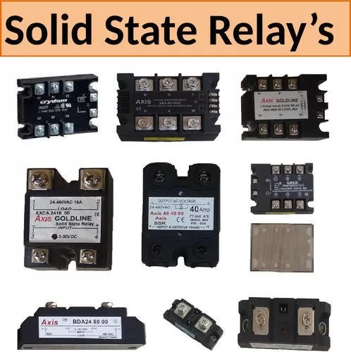
Solid State Relays (SSR):

  • Working principle: It relies on electronic control to switch the current, and does not contain moving mechanical parts.
  • Advantages:
    • Switching speed: It is faster to switch between states (open/close) since there are no mechanical parts.
    • Durability: It does not contain a moving part, which allows it to withstand repeated operation without significant wear.

Various uses:

  • Electromechanical: They can be used in applications requiring large currents and high endurance, such as controlling electric motors.
  • Solid State: Used in electronic control and applications that require fast and precise switching, such as controlling light bulbs or electronic motors.

Additional notes:

  • Life expectancy: It is affected by the presence of moving parts in electromechanical relays, while solid state relays are more stable.
  • Maintenance Cost: Electromechanical relays may need more maintenance due to normal wear and tear, while solid state relays are less affected by corrosion.

The stage type is selected based on the specific application requirements and operating conditions.

Electromechanical relays:

the frame:

  • A heavy-duty frame houses and supports the relay parts.

File:

  • A wire wrapped around a metal core causes an electromagnetic field.

the engine:

  • The motor opens and closes the contacts, and the spring returns the motor to its original position.

Contacts:

  • It includes two circuits: the activation circuit and the communication circuit.
  • Installations such as SPST or DPST vary depending on the number of contacts and spacers.

Number of dividers and columns:

  • Break: The number of positions the relay is separated (single or double).
  • Polarity: The number of insulated circuits through which the relay passes.
  • Throw: The number of contact positions per electrode (control one or two circuits).

comments:

  • Connections to SP or DP directions determine the control capability of one or two circuits.
  • The relay is energized when current passes through the coil, the magnetic coil attracts the armature.
  • Relays can be configured to perform various functions by selecting appropriate dividers and columns.
  • Ratings such as SPST or DPST express the way the relay is connected and the number of circuits available.

Additional points:

  • A good understanding of operating principles and configuration helps in selecting the appropriate relays for the application.
  • The mechanical and electrical characteristics of relays can guide use and maintenance.
  • Concepts such as pole and throw explain how a relay can control circuits and be configured to meet needs.

Types of relay:

1. General purpose relays:

  • Type:Electromechanical.
  • Operation: by magnetic coil.
  • Capacity: It can control currents ranging from 2A-30A.
  • Uses: To control starters and other industrial components.
  • Features: Economical, easy to replace, and allows for wide transformer configurations.

2. Machine control relays:

  • Type:Electromechanical.
  • Operation: by magnetic coil.
  • Operating current and voltage:Shared with general purpose relays.
  • Capability: Control starters and industrial components with additional media for expansion.
  • Features: Durable, expandable by adding accessories such as poles, contacts, etc.

3. Reed Relays:

  • Type:Electromechanical (Reed Switch).
  • Operation: with a magnetic field.
  • Design:Small and compact with NO contact.
  • Features: Sealed in a glass envelope, works quickly, durable and operable in harsh environments.
  • Uses: Replacement of industrial components such as solenoids, contactors and starter motors.

Additional notes:

  • Machine control relays have the advantage that their functionality can be expanded using accessories.
  • Reed Relays are used in harsh environments and are characterized by their durability and ability to operate quickly.
  • Reed technology provides features such as corrosion resistance and durable operation in ambient pollution conditions.
  • A good understanding of the design and proper use of each type of relay leads to an effective and appropriate selection for your application.
What is the difference between contactor and relay?

Solid state relays:

Solid-state relays feature an advanced configuration that includes three main circuits:

1. Input circuit:

  • Function: Similar to the function of an electromechanical relay coil.
  • Details: Activated when a voltage higher than the specified pickup voltage is applied.
  • Input voltage: Typically between 3 VDC and 32 VDC.
  • Reaction: Activation is deactivated when the voltage drops below the specified minimum.

2. Control circuit:

  • Function: Determines when to activate or deactivate the relay.
  • Details: It works as a link between the input and output circuits.
  • Interaction: Controls the activation and deactivation of the output component.

3. Output circuit:

  • Function: Operating the load and achieving the same purpose as mechanical contacts in electromechanical relays.
  • Additional details: Usually has only one output contact.

Additional notes:

  • Voltage Range:The voltage range of 3 VDC to 32 VDC is mostly used with solid-state relays, making them suitable for most electronic circuits.
  • The role of the control circuit:The control circuit performs a specific function in regulating the relay interaction between the input and output circuits.
  • Output circuit: drives the load and performs a role similar to contacts in electromechanical relays.

These components enhance the efficiency and reliability of solid-state relays in electronic control.

Types of relays: solid state

1. Zero switch relays:

  • Turn on the load when the control voltage is applied (minimum turn on).
  • Turning off the load when the control voltage is removed, and the current in the load approaches zero.
  • most used.

2. Instant start relays:

  • They turn on the load immediately when there is a pickup voltage.
  • They allow the load to be triggered at any point in the ascending and descending wave.

3. Peak switching relays:

  • They turn on the load when the control voltage is present at its peak.
  • They turn off when the control voltage is removed, and the current in the load approaches zero.

4. Analog switching relays:

  • They have an infinite number of output voltages within the rated range.
  • It has a synchronization circuit that controls the output voltage.

Time monitoring:

  • The analog switch type relay allows for a time Ramp-Up function, which means time is available to be on the load.
  • They turn off when the control voltage is removed, and the current in the load is close to zero.

Relays contact life

The life of relays depends on the quality and efficiency of the contacts in them. Here are some concepts regarding the life of relays:

  1. Burning contacts:
    • When contacts in relays are exposed to frequent friction or high electrical current, burn-out conditions may occur.
    • Once burnout occurs, it is necessary to replace the contacts or the relay as a whole.
  2. Mechanical life:
    • Indicates the number of operations (opening and closing) that can be performed by the contact without electrical current.
    • Current relays maintain a relatively long mechanical life, which can reach 1 million operations in some cases.
  3. Life span of relays:
    • It expresses the number of operations (opening and closing) that can be performed by the contacts under the influence of an electric current.
    • It is affected by operational conditions and current rating.
  4. Electrical life rates:
    • Depends on current strength and environmental conditions.
    • The electrical life ratings of relays may range from 100,000 operations to…

The life of relays is an important factor in designing electrical circuits and determining the sustainability of electrical systems.

The difference between contactor and relay

ContactorThe relay
FunctionIt is used to operate electrical loads with low and high currentsIt is used in control circuits to give an electrical signal to another component
the sizebig sizesmall size
Ampere capacityFrom 9 amps and aboveUp to 10 amps
Contact pointsIt contains main open contact points in addition to auxiliary pointsIt contains only auxiliary (control) contact points (open and closed)
ApplicationsIt is used in turning on and off power circuits, such as: turning on and off electric motors (1 phase/3 phase), capacitors, heaters and lighting.It is used in control circuits to give a control signal to an element or another circuit
Additional help pointsAdditional auxiliary points can be installed on itHelp points cannot be added to it

If you have any inquiry, please contact us freely and we will be happy to serve you.
What is the difference between contactor and relay?

Gahzly website for purchasing electrical appliances

When we say Gahzly website, we are talking about one of the most famous Arab websites that was able, in a very short period of time, to achieve a very large demand for purchases from it by people from various parts and sectors of the Arab world.

On the Gahzly website, you will find a joint look and all the products that you may need in your home, starting with those for kitchens or bathrooms, but even those for gardens, you will find them on this wonderful site.

So, if you were lost before and did not know where to go to buy your products on the Internet, now you have the perfect solution, and all you have to do is go to the Gahzly website and start choosing the products you want.

What is the difference between contactor and relay?What are the features of Gahzly?

Since we are talking about a site that is preferred by many people around the world, there is no doubt that it is a site full of various features and characteristics. Therefore, we have decided to devote our next paragraph to pointing out the most prominent features of the Gahzly site.

One of the most prominent features of the site is the proportionality of prices. On the Gahzly website, you do not have to worry about the imaginary prices of the products, as is the case with most sites that display their products on the Internet.

The price of delivering products is very reasonable and not expensive, and the site accepts delivery to various countries, without forgetting that it accepts free shipping on some products.

One of the features of the site is also the high quality of its products, as it is impossible to find a poor quality product. Rather, the Gahzly website deals with the major companies, Philips, for example, and other famous brands, so you must remove from your mind the idea of ​​the poor quality of one of the products. Another advantage of the site is that it does not specialize in one type of product, but rather you will find various types of products on it, for example, electrical appliances, hand tools, mechanical devices, paints, packages for establishing apartments, and many other types.

Gahzly website also accepts what is known as the shopping cart, which makes it easy for you to filter the products you want to buy and put them in one package in order to be able to pay with the click of a single button.

Accepts multiple payment methods.

What is the difference between contactor and relay?

We are pleased that you visit our social media pages, where we publish exclusive offers on our website.

Our Facebook page Here.

Our Twitter account Here.

Leave a Reply