


Schneider Electric

Price range: 3.449,28 EGP through 26.430,45 EGP
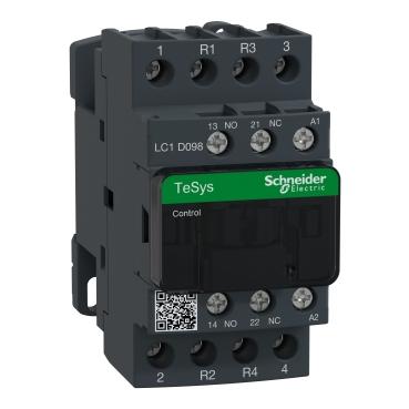
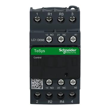
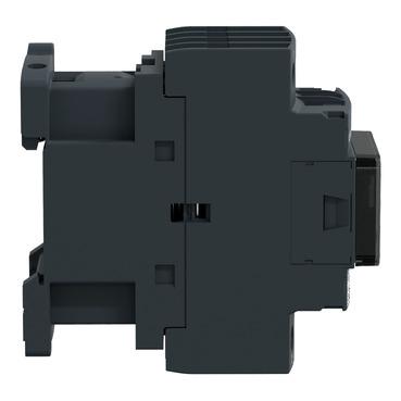
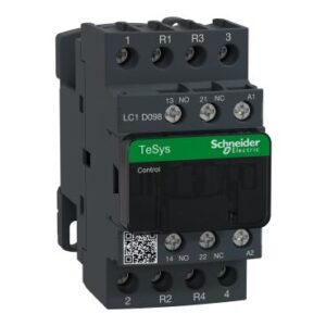
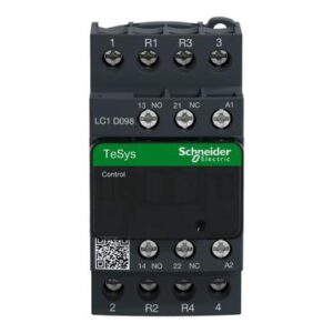
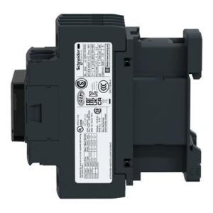
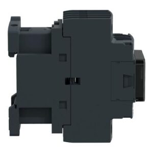
Comprehensive guide to the Schneider Electric four-pole contactor (Schneider AC-3 4P Contactor – 2NO + 2NC)
The industrial contactor in theAC-3four-pole (4P) configuration with integrated auxiliary contacts (2NO + 2NC) fromSchneider Electricis a key component in automatic-control panels for switching three-phase motors with a neutral conductor, or for managing mixed inductive and resistive loads in industrial and commercial installations. TheAC-3utilization category is specifically designed to withstand the high starting-current stresses associated with regularly starting and stopping squirrel-cage induction motors. The four poles (4 Poles) provide flexibility to switch the three phase conductors together with the neutral where required. The integrated auxiliary contacts, 2 Normally Open + 2 Normally Closed, support electrical interlocking, indication, status signalling, and automatic-control circuits.
Integration with modern control technologies
Although the contactor is an electromechanical device, it can be integrated effectively with modern control systems:
- PLC integration:The contactor coil can be connected to PLC outputs, either directly when a 24V DC coil and the PLC output rating are compatible, or through an appropriate interposing relay.
- Feedback signals:The auxiliary NO/NC contacts can provide actual contactor status feedback to SCADA, PLC, and other monitoring systems for operation confirmation and status supervision.
Please sign in to submit a product report.
Technical specifications
A single structured view of reviewed Product Entry data and canonical WooCommerce specifications.
- كيلو وات
- 11kw، 18.5kw، 37kw، 4kw، 5.5kw، 7.5kw
- Description
- Reviews
Description
Comprehensive guide to the Schneider Electric four-pole contactor (Schneider AC-3 4P Contactor – 2NO + 2NC)
Physical and operating architecture of the contactor
The contactor converts a low-power electrical control signal into electromagnetic mechanical motion that opens and closes higher-power circuits. Its internal construction consists of several main components working together:
1. Electromagnetic coil (A1/A2)
The coil generates the magnetic field when the specified control voltage is applied, such as 220V AC or 24V DC. It consists of copper winding around a fixed magnetic core. When energized, the magnetic field attracts the moving core.
2. Fixed and moving magnetic core (Core& Armature)
The magnetic core is typically built from laminated electrical steel to reduce magnetic losses and eddy currents. In AC coils, a shading ring may be used to reduce vibration and humming while the coil is energized.
3. Four main poles (4 Main Poles)
The device includes 4 main poles designed to carry the primary load current. In versions configured with 2NO + 2NC main or auxiliary contacts:
Normally Open contacts (NO):They are open when the coil is de-energized and close when the magnetic mechanism is energized, allowing current to flow to the connected circuit.
Normally Closed contacts (NC):They are closed in the normal de-energized state and open when the coil is energized.
4. Arc chute
When the main contacts open under load, an electrical arc can form as the air between the contacts becomes ionized. The arc chute uses metal plates to divide and cool the arc rapidly, reducing damage to the contact surfaces.
Contactor technical specification table
| Technical property | Value / description | Practical benefit to the user |
|---|---|---|
| Manufacturer | Schneider Electric | Supports product traceability, spare-parts availability, and compliance with the manufacturer’s applicable standards. |
| Number of main poles | 4 poles (4P) | Allows the three phase conductors (L1, L2, L3) and neutral (N) to be switched together where required by the circuit design. |
| Main utilization category | AC-3 / AC-1 | Suitable ratings may cover motor-switching duties such as AC-3 and resistive or low-inductance loads such as AC-1, subject to the exact contactor rating. |
| Integrated auxiliary contacts | 2NO + 2NC | Provide flexibility for electrical interlocking, indication, and PLC integration. |
| Coil voltage | Available in variants such as 24V, 110V, 220V, or 380V AC/DC, depending on the exact model | Allows selection to suit the control-voltage system used in the panel. |
| Mechanical service life | Up to 15 million operating cycles | Supports long mechanical service life and can reduce replacement frequency in repetitive-control applications, subject to operating conditions and the manufacturer’s rating. |
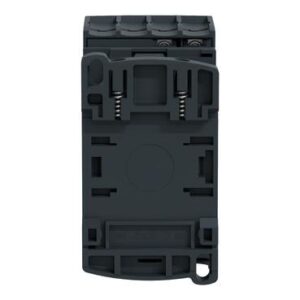
| Mounting method | 35mm DIN rail or screw mounting | Supports straightforward installation in a range of electrical panels. |
| Protection rating | IP20 | Helps reduce accidental direct contact with energized internal parts when correctly installed inside a suitable enclosure. |
Detailed explanation of technical specifications and benefits
AC-3 utilization category:AC-3 means the contactor is intended for starting and stopping induction motors whose starting current may be approximately 5 to 7 times the rated current. This utilization category requires contacts designed to withstand the switching arc created during making and breaking without welding or premature damage.
AC-1 utilization category:AC-1 applies to non-inductive or slightly inductive loads, such as many heating and resistive-load applications, where switching duty is less severe than typical motor-starting duty.
Auxiliary-contact configuration (2NO + 2NC):
2NO (Normally Open):Normally open auxiliary contacts can be used for PLC feedback, control logic, or an ON indicator showing that the contactor is energized.
2NC (Normally Closed):Normally closed auxiliary contacts are commonly used in electrical interlocking circuits between two contactors, such as reversing or changeover circuits, to prevent both contactors from being energized at the same time.
Advantages and limitations of the Schneider four-pole contactor
Advantages
High reliability:Designed with materials suitable for the thermal and mechanical stresses of its rated switching duty.
Four-pole isolation including neutral:The four-pole arrangement allows the neutral conductor to be switched together with the phases where the electrical design requires it.
Integrated auxiliary contacts:The built-in 2NO + 2NC auxiliary contacts can reduce the need for separate auxiliary-contact accessories in compatible control circuits.
Flexible standard mounting:Supports straightforward mounting on a standard DIN rail where specified for the model.
Effective arc control:The arc-control design helps protect the internal contacts during switching within the device ratings.
Limitations
Initial cost:Typically higher than unbranded or economy alternatives.
Size:May require slightly more panel space than a comparable three-pole (3P) contactor.
Suitable and unsuitable applications
Suitable applications
Three-phase loads where neutral switching is required:For equipment or circuit designs that require the neutral conductor to be switched together with the phase conductors.
Automatic Transfer Switch (ATS) systems:In transfer systems between utility and generator supplies where the electrical design requires switched neutral to prevent unintended neutral or earthing interactions.
Industrial heaters and large resistive loads:Controlling three-phase heating groups distributed across 4 poles.
Complex automatic-control panels:Applications requiring multiple interlocks and status signals for PLC-based or building-control systems.
Applications where it is not suitable
High-voltage DC loads (DC-3 / DC-5):unless the contact arrangement and series connection are specifically permitted by the manufacturer’s DC switching instructions.
Direct switching from sensitive electronic outputs:Use an appropriate interface relay when the contactor coil voltage or current is not compatible with the controller’s digital output rating.
Operation and installation method
Mechanical and electrical installation steps
Isolate the electrical supply:Switch off the main protective device and confirm absence of voltage with a suitable tester or multimeter before installation.
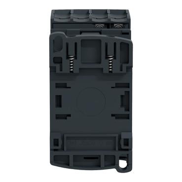
Mechanical mounting:Mount the contactor on the 35mm DIN rail and confirm that the retaining clip is fully engaged.
Connecting power terminals:
Connect the incoming supply conductors to the designated upper terminals, such as 1/L1, 3/L2, 5/L3, and 7/L4, according to the product marking.
Connect the outgoing load conductors, such as the motor or heater circuit, to the corresponding lower terminals 2/T1, 4/T2, 6/T3, and 8/T4.
Connecting the control circuit:
Connect the control supply for the coil to terminals A1 and A2 using the voltage specified for the exact coil model.
Use the auxiliary contacts, such as 13-14 / 23-24 for NO contacts and 11-12 / 21-22 for NC contacts where applicable, for indication or interlocking circuits according to the actual terminal markings.
Tightening screws:Use a suitable screwdriver and tighten the insulated terminals to the torque recommended by Schneider for the exact model, stated in the source as typically between 1.2 and 1.7 N·m, to reduce heating caused by loose connections.
Safety instructions and warnings
Important safety warning:Industrial electrical systems can cause severe injury or death if appropriate electrical safety procedures are not followed.
Isolation and Lockout/Tagout (LOTO):Apply the site’s Lockout/Tagout procedure before beginning installation or maintenance work.
Voltage matching:Confirm that the Coil Voltage marked on the contactor matches the available control-circuit voltage exactly.
Short-circuit and overload protection:A contactor does not replace an MCB/MCCB or an overload relay. The circuit and motor must be protected by appropriately selected short-circuit and overload protective devices.
Do not force the mechanism manually under load:Avoid manually forcing the contactor moving mechanism while the circuit is energized. Any test procedure should follow the manufacturer’s instructions and use appropriate insulated tools and safety controls.
Maintenance, cleaning, and service-life considerations
Periodic terminal inspection:Continuous mechanical vibration can loosen terminal connections; inspect and retighten the screws periodically every 6 months.
Dust cleaning:Dust accumulation inside the arc chambers or on the magnetic surface can cause humming (Humming) and increase coil temperature. Use dry compressed air for cleaning.
Inspecting auxiliary and main contacts:If the contacts turn dark black due to repeated electrical arcing, check the contact gap and replace the affected part if necessary.
Temperature monitoring:Use a thermal camera (Thermal Imager) while operating under load to detect any abnormal hot spots (Hotspots).
Comparison between Schneider contactors and other alternatives
| Comparison criterion | Schneider 4P contactor (AC-3) | Unknown / economy contactors | Three-pole contactor (3P) |
|---|---|---|---|
| Neutral disconnection | The neutral is fully disconnected together with the three phases | Varies according to the number of poles | Does not disconnect the neutral line |
| Reliability and safety | Complies with IEC/EN 60947 standards | May not comply with precise safety standards | High with established brands |
| Contact service life | High-quality silver alloys that resist welding | Low-quality alloys that weld quickly | High with established brands |
| Acoustic stability | Advanced humming suppression system | Noticeable humming and vibration over time | Requires a good shading ring |
Integration with modern control technologies
Although the contactor is an electromechanical device, it can be integrated effectively with modern control systems:
PLC integration:The contactor coil can be connected to PLC outputs, either directly when a 24V DC coil and the PLC output rating are compatible, or through an appropriate interposing relay.
Feedback signals:The auxiliary NO/NC contacts can provide actual contactor status feedback to SCADA, PLC, and other monitoring systems for operation confirmation and status supervision.
Important tips before purchase
Selecting the correct current rating:Determine the rated load current (In) and make sure the contactor rating in the required utilization category (AC-3 or AC-1) covers this current with a 20% safety margin.
Checking the coil voltage (Coil Voltage):Confirm whether your control circuit operates at 220V AC, 24V DC, or another voltage.
Reviewing the number and type of auxiliary contacts:Make sure the (2NO + 2NC) configuration meets your control and interlocking circuit requirements.
Verifying product authenticity:Buy from authorized distributors to avoid counterfeit products, as genuine products provide safer materials and compliance with specifications.
Comprehensive summary and purchase decision
TheSchneider four-pole contactor (AC-3 4P – 2NO + 2NC)An integrated engineering choice for users seeking safety and reliability when controlling three-phase electrical loads together with the neutral. With Schneider Electric manufacturing quality, integrated auxiliary control contacts, and the ability to withstand high inrush currents, this device provides dependable protection and operational continuity for sensitive industrial and commercial applications.
Be the first to review “Schneider Electric”
You must be logged in to post a review.
Product Questions & Answers
No questions yet. Ask the supplier about specifications, compatibility, certifications or installation requirements.

Reviews
There are no reviews yet.