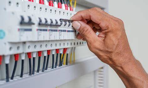
Gahzly’s Guide to Grounding Systems: Types, Components, Calculations and Measurements 2023
Gahzly's Guide to Grounding Systems: Types, Components, Calculations and Measurements 2023 Types of grounding systems Types of grounding systems according to IEC: 1) TT system 2) it system 3) TN system: • TN-C system • TN-S system • TN-CS system Neutral and…
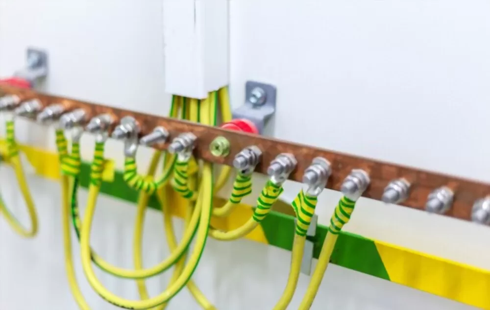
Gahzly’s Guide to Grounding Systems: Types, Components, Calculations and Measurements 2023
Types of grounding systems
Types of grounding systems according to IEC:1) TT system
2) it system
3) TN system:
• TN-C
system • TN-S
system • TN-CS system
Neutral and Bare Conductor Part Connections:
The first letter : the relationship of the power system to grounding:
T : direct neutral to grounded connection;
The first : a neutral isolated from earthing or connected to earthing with resistance.
The second letter : the relationship of the exposed conductive parts of the earthing installation:
T : direct electrical connection of the exposed parts conductive to earth.
N : Direct electrical connection of exposed parts connected to neutral.
N & PE Connectors Arrangement:
Suffix letter(s) (if any) : Arrangement of neutral and protective conductors:
S : Separate neutral and protective (N & PE) conductor.
C : Combined neutral and protective conductor (PEN conductor).
CS : TN-C near source, TN-S near loads.
TT system
The power supply (or the neutral point of the supply transformer) is connected directly to a ground electrode, the exposed conductive parts of the consumer-side installation being grounded through a separate ground electrode that is electrically independent of the supply electrode.
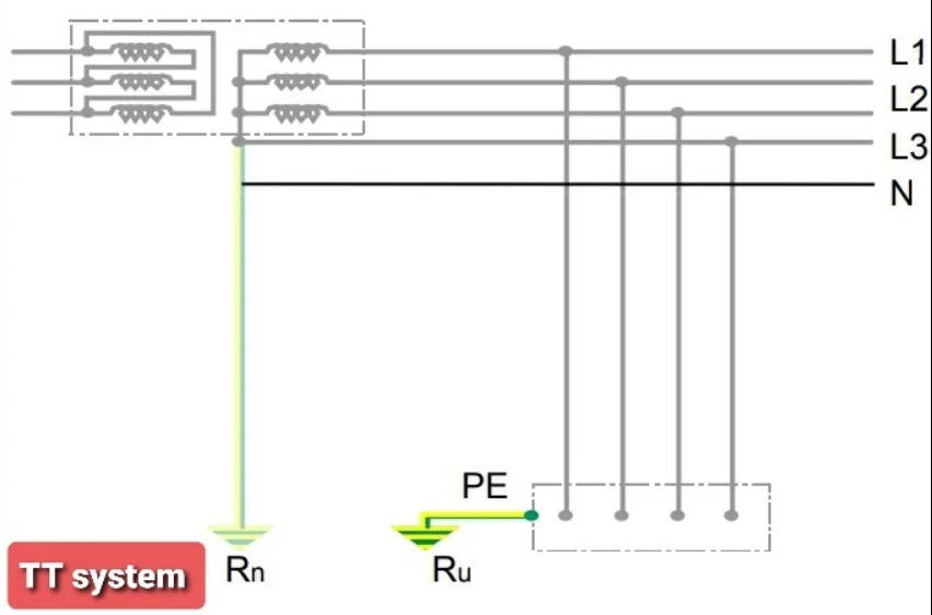
– In the event of an insulation fault, the possibility of suddenly exposed conductive parts increases causing a dangerous condition of electric shock, and this can be avoided by using an RCD with proper sensitivity in the touch voltage function.
To ensure safety conditions in the facility, the grounding values must comply with:
RA x I∆n ≤50V
– RA = the value of the grounding resistance of the installation.
– I∆n = residual value of the operating current of the RCD.
Advantages of the TT system
2) Fault currents are very weekly and cannot be energized on over current protection devices and special devices (RCDs) can be used to detect the leakage current to grounding and interrupt the circuit.
3) The safety of people is ensured through the use of an RCD
5) The system can be easily extended without having to calculate lengths
6) Faults in the medium voltage network are not transmitted to the low voltage network
7) Faults in the LV network are not transmitted to other LV customers.
8) In the event of a neutral break, the TN system does not cause any potential surge of the conductive parts exposed with the neutral conductor.
1) An RCD must be installed on each outgoing line to achieve horizontal discrimination which increases the cost of the system.
2) In some cases, it is difficult to ensure vertical discrimination of the RCD.
3) Excess voltages may occur between all live parts and between live parts and PE conductor.
4) The safety level is subject to the grounding resistance value of the system.
TT system applications
system it
In this system, the power supply or the neutral point of the secondary winding of the supply transformer is either isolated from grounding or connected to a ground electrode through a high amperage resistance and the exposed conductive parts of the electrical installation are connected to a separate ground electrode.
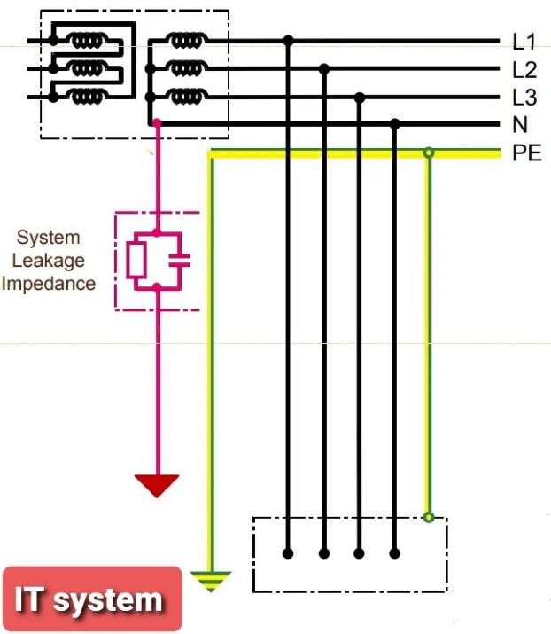
– The grounding system of it does not have a direct connection between the live parts and the grounding.
– In the event of an insulation failure, the value of the fault current is not high enough to generate a dangerous voltage.
– On the occurrence of the first fault, protection against indirect contact shall be provided by an isolation monitor which shall provide a visual and audible alarm.
In the event of a second fault, the service is interrupted by breakers according to the following tripping conditions:
To ensure safety conditions in the facility, you must adhere to the following:
RA x ID ≤ 50V
– RA = the value of the grounding resistance of the installation.
-id = the current value of the error for the first error.
Advantages of it
2) Optimum safety during the first mistake
4) When the first fault occurs, there is no need to interrupt the service and the isolation monitors issue an alarm
system defects
2) Dangerous touch voltage in the event of a double fault.
4) Network insulation should be monitored permanently.
it
TN system
In this system, the power supply (or the neutral point of the secondary winding of a supply transformer) is directly grounded at one or more points, and the exposed conductive portion of the electrical installation is connected to that point via a protective conductor (PE).
– There are three types of TN systems: TN-C, TN-S and TN-CS
TN-C system
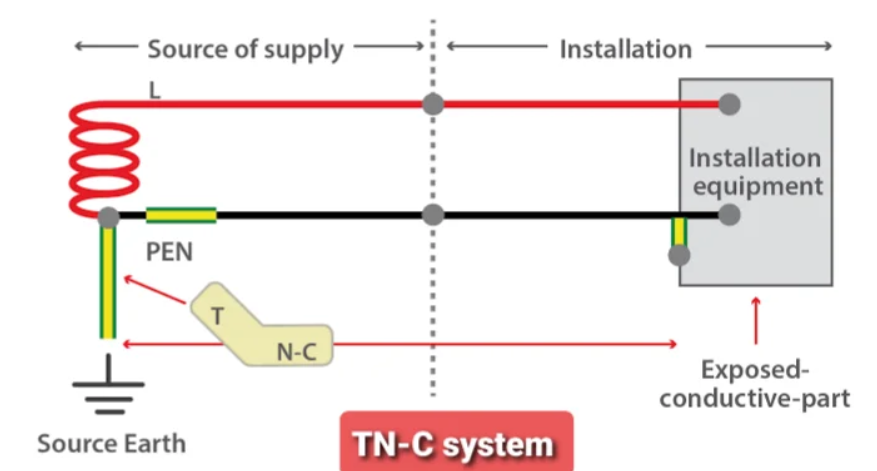
• In this system, a common conductor is used for both the neutral conductor (N) and the protective conductor (PE) all the way from the supply transformer to the consumer building, and this common conductor is called (PEN) or “protective earthing and neutral conductor”
TN-S system
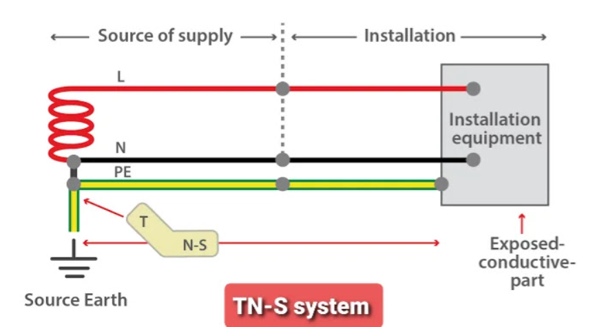
• In this system, the neutral (N) and protective earth (PE) conductors are separated throughout the system from the supply transformer to the consumer’s building and are not connected at any point within the building.
The separate protective earthing conductor can take the form of a metal sheath or shield for the underground supply cable.
TN-CS system
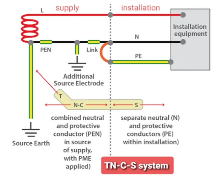
• Part of the system uses an integrated PEN conductor, which at some point is divided into a separate protective earth PE conductor and N neutral conductors, the integrated PEN conductor is used between the transformer or power supply and the entry point of the building while the separate conductors (PE & N) are used inside the building.
This is commonly referred to as Protective Multiple Earthing (PME).
Advantages of the TN system
1) In the event of an insulation failure, the error or touch voltages in the TN grounding system are smaller than in the TT system, this is due to the lower voltage in the phase conductor and lower resistance of the PEN conductor compared to the TT grounding system.
Disadvantages of the TN system
1) Faults in the medium voltage network may transmit to the low voltage earthing network causing touch voltage at the consumers.
2) In the event of a neutral break, the TN system causes a potential surge of the conductive parts exposed with the neutral conductor.
3) Any modification in the low-voltage network leads to an increase in the resistance of the fault circuit, and therefore protection devices must be installed.
TN system applications
grounding methods
Pipe grounding
This is the best and most popular grounding system compared to other systems suitable for the same soil and moisture conditions.
In this method a galvanized iron pipe of approved length and diameter is used as a ground electrode and such pipe shall have holes punched at regular intervals along the length and shall be narrow at the lower end.
GI pipe is run vertically and straight in permanently moist soil and its size depends on the value of fault current to be conveyed and the type of soil.
The diameter of the tube is usually 38.1 mm and the length is 2 meters for normal soils, and the length of the tube should be increased to 2.75 meters in the case of dry and rocky soils.
The depth at which the pipe should be buried depends on the soil moisture condition.
The lower part of the tube is surrounded by small pieces of coke or coal and salt with a thickness of not less than 15 cm around the tube. Alternate layers of coke and salt are used up to the top of the tube as the coke retains the mixture and increases the effective area of grounding and the salt reduces the resistance to grounding.
Another GI tube with a diameter of 19.05 mm and a length of 1.25 m (or longer) is connected at the top of the GI tube (ground electrode) with the help of a telescoping socket.
A funnel is attached to the top of the tube with a diameter of 19.05 and the top of the tube with the funnel is placed inside a grounding hole measuring 30 cm x 30 cm x 30 cm (1 ft x 1 ft x 1 ft) and the four ends of the pit have concrete or brick walls and are covered From above with a plate of cast iron.
During the dry summer, the grounding resistance increases due to the decrease that occurs in the watery soil, in order to increase the conductivity and obtain an effective soil. 19mm, which is further attached at the top of the GI tube.
GI wire or strip of GI earthed wire is carried in GI tube (diameter 12 mm) at a depth of 60 cm below ground level, then this GI wire is fixed at the top of GI tube with the help of nuts and bolts.
The cross-sectional area of the ground wire must be sufficient to carry the fault current safely.
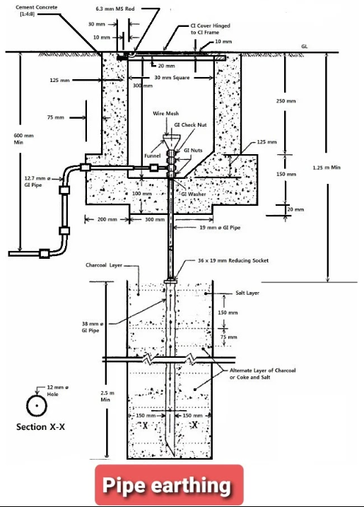
plate grounding
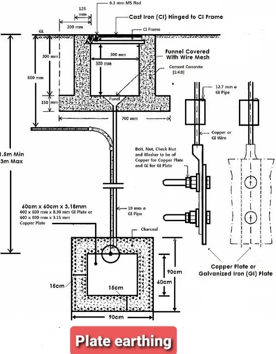
In this method, a plate is used as a ground electrode and the plate is made of one of the following two materials:
1) A sheet of galvanized iron and must be at least 60 cm x 60 cm x 6.35 mm (2 ft x 2 ft x 1/2 in) in size.
2) a copper plate and the size shall be 60 cm x 60 cm x 3.18 mm (2 ft x 2 ft x 1/8 in).
In both cases, the plate shall be buried vertically in the earthing at a depth of not less than 3 m (10 feet) from the earthing level.
Then the plate is surrounded by small pieces of coke or charcoal and salt to a thickness of at least 15 cm
A GI pipe of 12.7 mm (1/2 inch) diameter shall be placed horizontally 600 mm below the grounding plane and then bent to be in a vertical position up to the top of the earthing plate and into this pipe, a ground wire made of the same material as that of the grounding plate shall be carried The grounding plate (copper ground wire for copper grounding plate and GI wire for grounding plate GI) from the main grounding rod up to the top of the plate and is firmly fixed to the grounding plate with the help of bolts, nuts and washers.
Another GI tube is placed at the top of the grounding plate and a funnel is attached at the top of this tube, the top of the tube with the funnel is placed inside a grounding hole (as above) and three or four buckets of water are poured into the funnel to maintain impedance Grounding at the lowest possible value.
strip or grounding wire
This method is used in rocky areas where excavation work is very difficult.
In this method, strips or wires are used which can be one of the following types or shapes:
- Minimum cross-section copper strips (25 mm x 1.6 mm)
- Galvanized iron strips of minimum cross-section (25 mm x 4 mm)
- Minimum cross-section copper conductors (3 mm²)
- galvanized iron conductors of minimum cross-section (6 mm²)
The length of the conductors or strips buried horizontally within the grounding shall not be less than 15 meters to obtain the required grounding resistance.
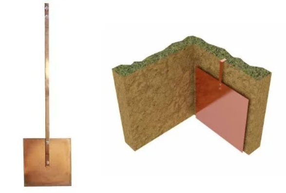
Earthing boards
Earthing panels shall be made of electrically annealed copper sheets or steel sheets with electrolytic copper bonding
Earthing panels are also used where there are highly resistive soils
The use of grounding plates as electrodes significantly reduces the grounding resistance in stone grounding because it increases the contact area between the electrode and the grounding.
The grounding is available in dimensions of 600 mm x 600 mm and 900 mm x 900 mm and copper thickness of 1.5 mm or 3 mm.
grounding network
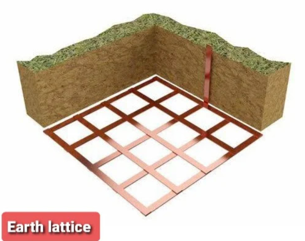
The grounding network is made of copper tape of various groups, and these copper tapes are made of highly conductive copper, electrolytic copper or electroplated copper.
Earthing mesh is often used for potential rating and is a preferred choice in telecommunication towers and other applications to reduce the risk of high steps and touch voltages that can cause problems for operators in situations such as high voltage switching.
Earthing mesh is used to provide a long-term, durable, and highly reliable grounding solution in high-fault current applications because it provides good grounding contact with a wide surface area of the surrounding soil.
The earthing grid is available in many sizes such as (500 x 500, 600 x 600, 900 x 900, 1000 x 1000) and with a thickness of 2 mm or 3 mm.
The earthing network provides high corrosion resistance, corrosion resistance and high electrical conductivity.
 river design
This method is the easiest and cheapest method of grounding because it does not require any excavation work.
It is suitable for sandy areas and used for temporary grounding purposes
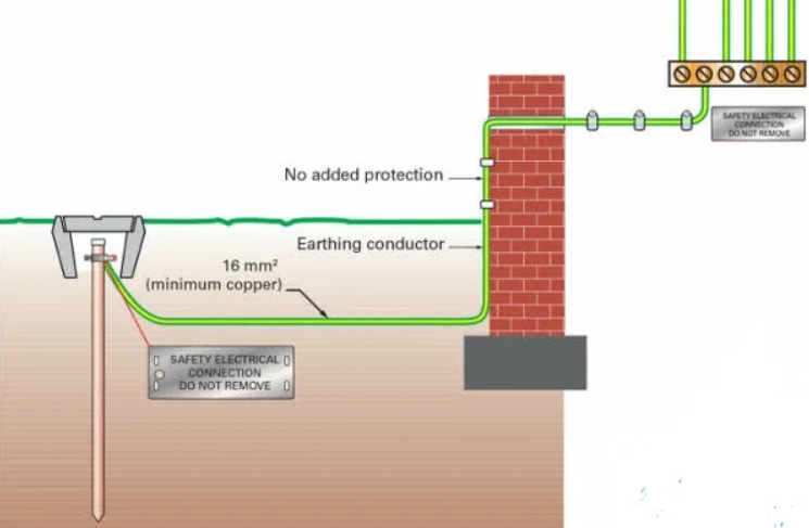
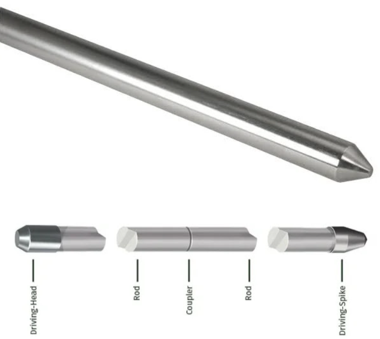
In this method, a ground rod with a diameter of 12.7 mm (1/2 inch), 16 mm (5/8 inch), or 19 mm (3/4 inch) made of galvanized steel, annealed copper, annealed copper, or stainless steel is directly pushed To manually grounded to a minimum depth of 2.44 m (8 ft) (as per NEC code)
The rod is hammered manually or with the help of a pneumatic hammer
The upper end of the rod shall be kept below the level of the grounding inside an earthing hole, the four sides of which shall be concrete or brick walls and covered with a plate of cast iron.
 Types of grounding bars
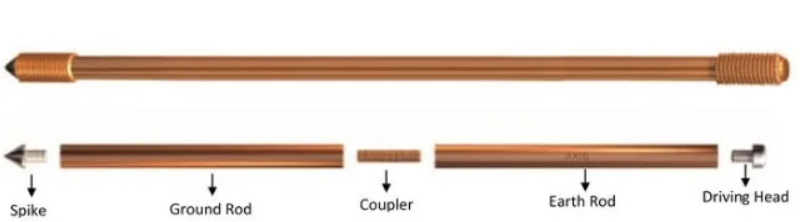
Solid copper grounding bars
It is made of extruded copper with high conductivity
Advantages
It is used for soils with high moisture and salt content and is highly corrosive
It is used where high fault currents are expected.
cons
Solid copper is a ductile metal that often flexes when driven into soil so it is not suitable for use where deep driving in earthing is required.
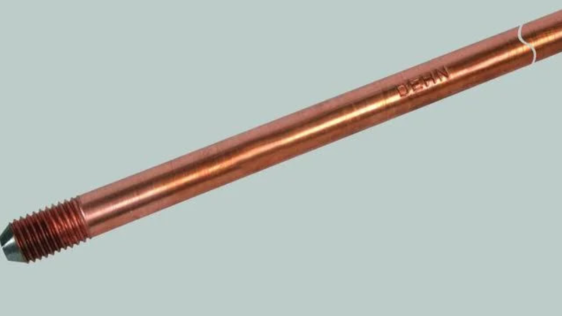
Copper bonded steel grounding rods
 Advantages
It is considered the most efficient and cost effective type of grounding rod.
It has high mechanical tensile strength and corrosion resistance at a lower cost compared to other types of grounding rods (solid copper or stainless steel).
The rod is usually treated to avoid oxidation of the copper bond.
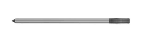
Galvanized steel grounding bars
The zinc coating will retard corrosion of the steel bar by providing a sacrificial barrier.
Advantages
It has good corrosion resistance and conductivity.
cons
It has the lowest corrosion resistance
It has lower electrical conductivity and poor current carrying capacity.
Applications
Stainless steel grounding bars
It is made of stainless steel bar
 Advantages
It is used when extreme corrosion resistance and high mechanical strength are required.
The stainless steel grounding rod is treated with an oxide coating that makes it more corrosion resistant than copper.
It is used to overcome many problems caused by galvanic corrosion that can occur between dissimilar metals buried close to each other.
The stainless steel grounding rod provides high mechanical strength so it is not likely to break or bend when driven into grounding even in rocky soil.
cons
It is the most expensive type of grounding rod.
The current carrying capacity of steel grounding rods is weak compared to copper grounding rods
Need
Earthing resistance of the grounding electrode
The resistance of the grounding electrode consists of three components: 1 The resistance of the electrode itself , which depends on the type of material it is made of and the contact resistance between the electrode and the connections to it (air wire and clamps) To keep this resistance as low as possible, the electrode must be made of a highly conductive material and must Avoid incorrect ends and fraying.
2 The contact resistance between the electrode and the grounding surrounding it is induced , so to reduce this resistance to a negligible value, the electrode must be free of grease and coating and the soil around the electrode must be tightly packed.
3 The resistivity of the surrounding soil which depends on the soil composition, soil temperature and the content of the softened soil.
NEC grounding electrode requirements
Pipe poles : The pipe or channel poles must not be less than ( 3/4 inch ) and require corrosion protection as they are made of iron or steel.
The thickness of the electrodes made of steel or iron plate shall be at least 6.4 mm (in ) but non-ferrous plate electrodes shall not be less than 1.5 mm ( 0.06 in).
Bar Poles : Iron or steel bars shall not be less than 15.87 mm ( 5/8 inch) in diameter and shall be galvanized to protect against corrosion.
The rod poles must meet the following requirements:
1) Their length should not be less than 1.5 meters ( 5 feet ).
2) It shall be driven, wherever possible, below the permanent level.
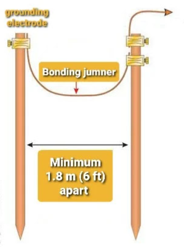
3) At least 1.8 meters ( 6 feet ) must be separated from any other electrodes including those used in signal circuits, lightning system or any other purpose.
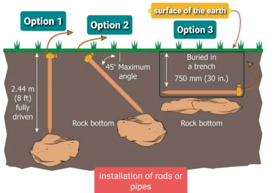
 4) It must be pushed to the ground, with a length of at least 8 feet ( 2.44 m ) in the ground (in contact with the soil).
5) If a rocky bottom is found before the grounding rod reaches 8 feet ( 2.44 m ) into the grounding, in this case it must be pushed into the grounding at an angle of no more than 45 degrees from the vertical to be at least 8 feet ( 2.44 m ) from Its length is in the ground.
6) If the rock bottom is so shallow that it is not possible to get 8 feet ( 2.44 m ) of the rod into grounding at an angle of 45 degrees , it is necessary to place the rod horizontally in a 2 feet ( 750 mm ) deep trench.
 How to reduce the resistance to grounding?
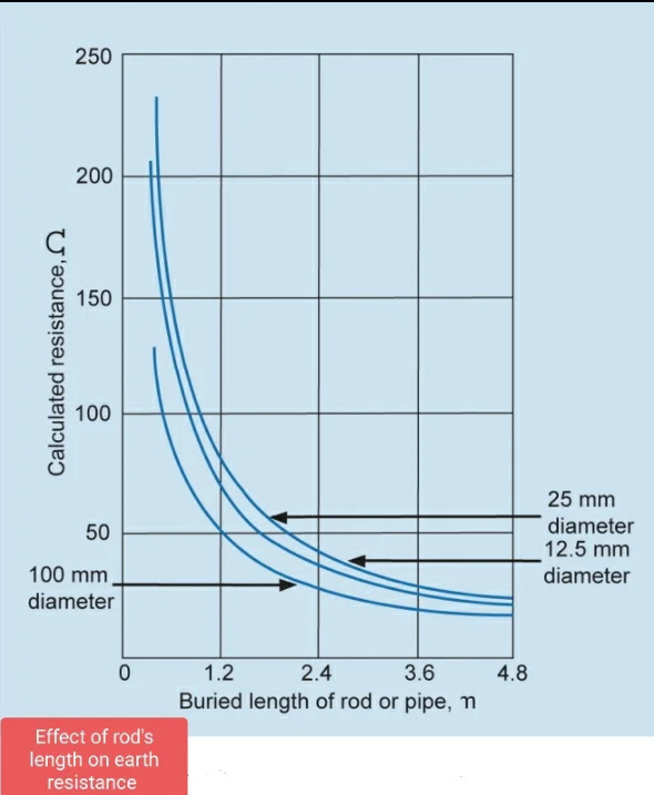
1) increasing the diameter of the grounding ro d
2) increasing the length of the grounding rod
3) using multiple rods in parallel
4) chemical treatment of the soil
Increase the diameter of the grounding rod
Doubling the diameter of the grounding rod will reduce the grounding resistance by about 10%.
This is not a cost effective solution because doubling the diameter of the rod means an increase in the weight and cost of the rod by about 400% while the grounding resistance will only decrease by 10%.
Doubling the length of the grounding rod will reduce the grounding resistance by about 40%.
 Using multiple bars in parallel
NEC requires that a single electrode with an earth resistance greater than 25 be augmented by an additional electrode.
– If two well spaced ground rods (of the same size and depth) are driven into the grounding, it will reduce the total grounding resistance by about 40%
– If three rods are used , the reduction of the grounding resistance will be 60%
– If four rods are used , The reduction will be 66%.
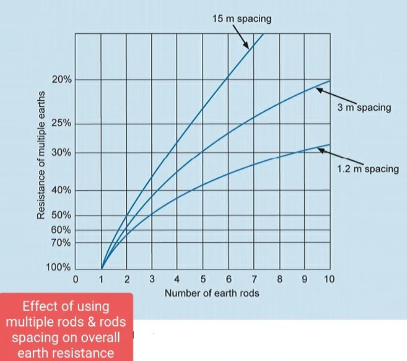
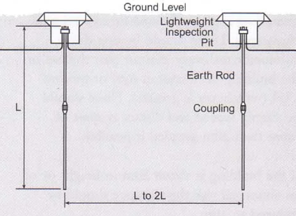
Two grounding rods must be spaced no less than the depth to which they are driven, or preferably twice the depth, and the NEC requires that the minimum spacing between two parallel rods driven into grounding be 6 feet .
Soil resistivity measurement (Wiener method)
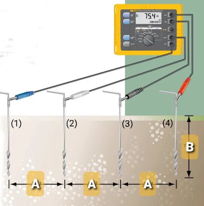 procedures
1) A four-terminal instrument such as a large grounding tester is used to measure the resistance to grounding
3) Use four separate jumper wires to connect the four poles to four terminals of the device as follows:-
- The outer two electrodes (1 and 4) are connected to the terminals labeled C1 and C2 (current terminals) on the device
- The two inner electrodes (2 and 3) are connected to the terminals labeled P1 and P2 (potential terminals) on the device
indicated to V1 and V2 to a very remote point.
Using Ohm’s law (R = V / I), the grounding tester will automatically calculate the grounding resistance and its value will appear on the screen of the tester.
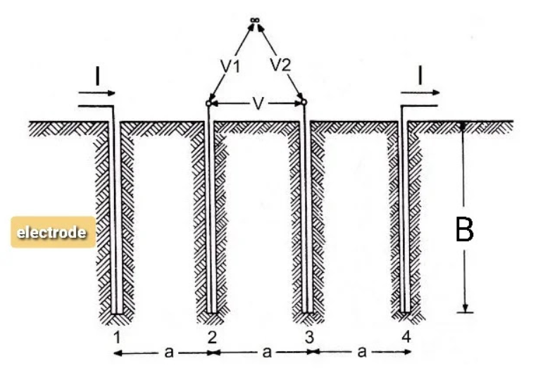 5) Use the following formula to calculate the value of the grounding resistance:
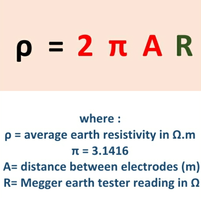 Case in point
 If the soil resistance measured by the bulky grounding tester is 20 Ω and the distance between the electrodes is 3 m . Calculate the resistivity of the soil??
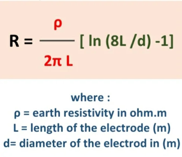
The grounding resistance can be calculated using the following equation:
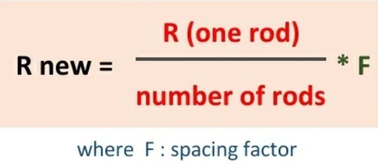
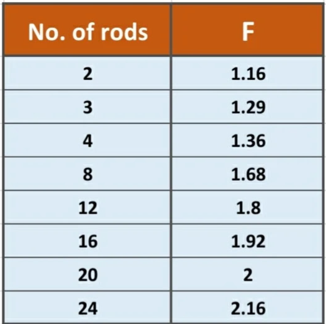
The following equation can be used to calculate the total grounding resistance of multiple bars:
Calculate the grounding resistance of a 3 m long, 16 mm diameter grounding electrode driven into 50 μm resistive soil .
This is a very large value, to reduce this resistance, another rod (electrode) is pushed parallel to the first rod.
Hence the equivalent earthing resistance will be:
Soil chemical treatment
Soil chemical treatment is a good way to reduce the grounding resistance of a grounding electrode in situations where we cannot drive the electrode to deeper depths due to hard bedrock and when the use of multiple rods is impractical.
Magnesium sulfate is the most widely used chemical compound because of its low cost, high electrical conductivity and least corrosive effect.
Synthesis of chemical compounds
2) Periodically provide the hole with a little water for good absorption of salts (chemicals).
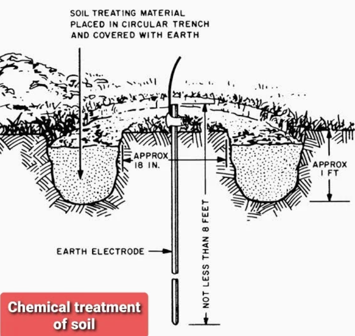
One good advantage of chemical treatment is that it reduces the seasonal variation in resistance that results from wetting and drying of the soil.
Bentonite is a yellowish-white sodium montmorillonite clay formed from altered volcanic ash.
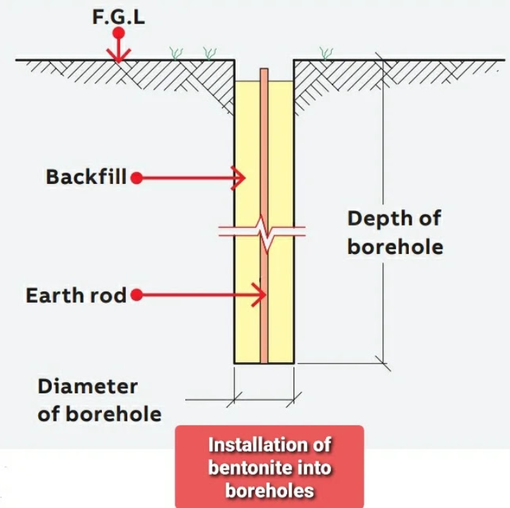
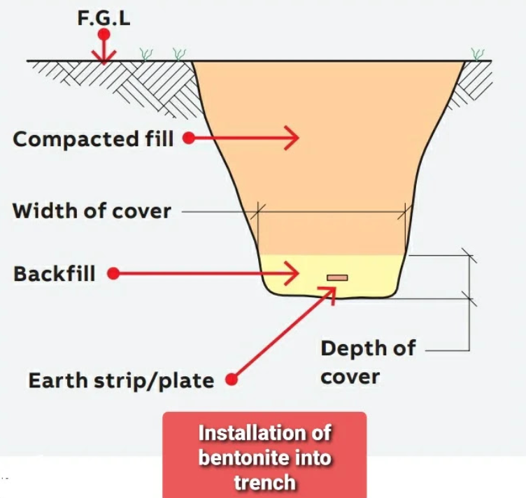
It is a seasonal retaining clay used to reduce contact earthing resistance and increase the effective size of earthing electrodes as a backfill for earthing rods installed in buried holes or as a coating for earthing conductors buried horizontally in a trench.
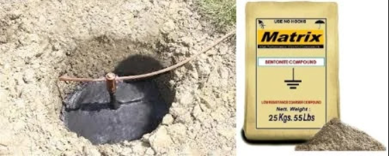
Advantages of bentonite as a backfill material
1 Bentonite is a super absorbent material in that when it comes in contact with water, it absorbs up to five times its own weight and expands up to thirteen times its original dry volume, increasing the walking area contact between the grounding electrode and the surrounding soil. which improves the overall grounding resistance.
2 Bentonite is strongly hygroscopic in water so it has a great ability to absorb water
3 Bentonite has the ability to absorb moisture from the surrounding soil and retain water or its moisture content for a long period of time at atmospheric pressure, and this will reduce grounding resistance.
4 Bentonite is a non-corrosive material even for a long period of time, so it protects the grounding electrode.
5 Bentonite is a stable material because it does not change its properties over time.
6 Bentonite is cost effective as we can obtain the required grounding resistance with a small amount when compared to other cement based solutions.
7 The resistivity of bentonite depends on its moisture content. Its resistivity varies from 3 ohms m in the wet condition and up to 18 ohms m in the dry condition.
8 Bentonite can be in the form of granules or powder, the granular form is preferred for filling trenches while the powder form is preferred for pouring into wells.
9 Due to the presence of impurities in the soil, the bentonite will retain the enclosure of the buried grounding rod or electrode and will not be washed away, thus we will not need to replace the bentonite
Bentonite 10 should not be used in very dry locations and free draining locations.
Bentonite composition
mixing bentonite
As a rule of thumb, assume an expansion ratio of 2:1
1 x 25kg = 1 cu ft or 0.0283 cubic meters (dry)
1 x 25 kg bag = 2 ft³ or 0.0566 cubic meters (wet)
Case in point
If we have 4 earthing rods inserted into the wells ( 10 cm wide , 3 meters deep ), calculate the amount of bentonite required to fill these wells??
Well volume = 2 x (r² x h) = 2 x (3.1416 x (0.1)² x 3)
number of bags = /0.0566 = bag
1) At the desired pole location, dig a hole 75-100 cm (3-4 inches) wide at a depth specified by the grounding system designer.
2) Insert the pole or rod vertically into the center of the well with the top of it at the right level for the wire connections.
4) Remove excess standing water from the trench
1) At the desired rod location, dig a trench 200-300 mm (8-12 in) wide at a depth of 600 mm below the grounding level or depth specified by the grounding system designer.
3) Apply another layer of bentonite 25-50 cm (1-2 inch) thick and make sure that the grounding tape is completely covered.
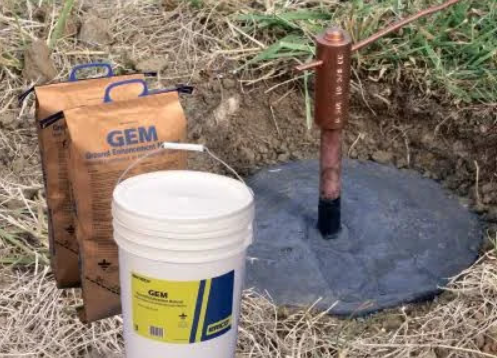
Advantages of GEM as an infill material
1 Ground Improvement Material (GEM) is a superconductive material that improves grounding efficiency especially in areas with poor conductivity and solves the most difficult grounding problems.
2 GEM is a low resistivity, non-corrosive, carbon dust-based material that improves grounding effectiveness, regardless of soil conditions. It is an ideal material to be used in areas with poor conductivity, such as sandy soils, rocky grounds, and mountain tops.
3 GEM contains Poltrand cement, which sets in 3 days and fully cures in 28 days, becoming a permanent, maintenance-free conductive concrete that will never leak or fade.
4 GEM is the best material you can use to reduce grounding resistance.
5 GEM maintains permanently low grounding resistance and provides high conductivity for the life of the earthing system once in its specified configuration.
6 GEM does not negatively affect the soil because it does not contain any hazardous chemicals so it will not pollute the soil or ground water.
7 GEM does not depend on the constant presence of water to maintain conductivity.
8 GEM is a permanent material that does not degrade, melt, or leak over time.
9 GEM does not require periodic charge handling nor replacement.
10 GEM works in all soil conditions regardless of the presence of water.
11 GEM is easy to install as it does not require any special tools and requires only one person to install and also requires no maintenance.
12 GEM can be easily installed in dry or slurry form.
13 GEM is not affected by freezing because freezing only increases resistance by 10-15%.
14 GEM is non-corrosive because it contains a corrosion inhibitor that forms a thin film on the surface of the rod creating a barrier against corrosion.
15 GEM reduces theft and vandalism as grounding rods and conductors are difficult to remove when set in concrete.
16 GEM has a very low resistivity (less than 0.02 Ohm m) which is only 1% of the resistivity of bentonite clay.
Applications
Grounding improver is the ideal material to be used in areas with poor conductivity, such as sandy soils, rocky grounds, and mountain peaks.
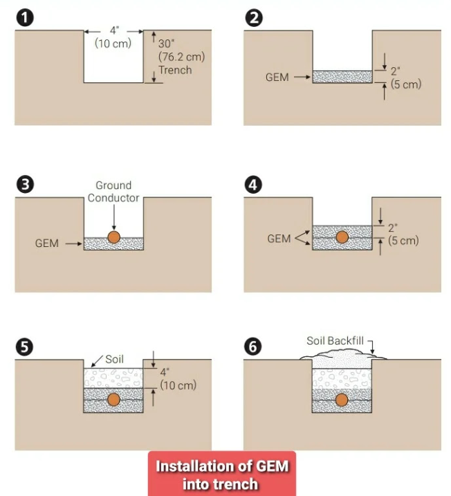
GEM installation
2) Mix the grounding reinforcement materials into a slurry using a cement mixer or mixing in a mixing bin or bucket. Use 1.5 to 2 gallons (5.7 to 7.6 liters) of clean water for each bag of grounding reinforcement.
Do not mix with GEM salt water.
3) Cover the bottom of the trench with a layer of 2 cm (5 inches) thick.
5) Apply another layer of grounding reinforcement material over the conductor and be sure to cover the entire conductor – about 2 inches (5 cm) deep.
Notes:-
- You should apply 10 cm (4 in) of insulation to the conductors and grounding rods sticking out of the grounding reinforcement, starting 2 in (5 cm) inside the grounding reinforcement.
- Excess standing water should be removed from the trench.
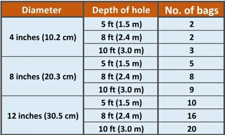
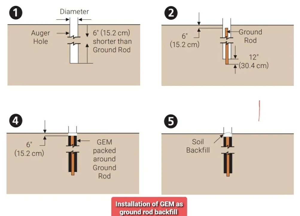
1) Drill: A hole 3 inches (7.5 cm) in diameter or larger to a depth of 6 inches (15 cm) shorter than the length of the grounding rod.
The top of the grounding rod will be about 6 inches (15 cm) below the grounding level.
3) Mix the grounding reinforcement materials into a slurry. Use 1.5 to 2 gallons (5.7 to 7.6 liters) of clean water for each bag of grounding reinforcement.
GEM installation in dry condition is acceptable for vertical earthing rod applications.
5) Wait 30 minutes to 1 hour and then fill the hole with backfill soil.
- You should apply 10 cm (4 in) of insulation to the conductors and grounding rods sticking out of the grounding reinforcement, starting 2 in (5 cm) inside the grounding reinforcement.
- Excess standing water should be removed from the trench
Gahzly website to buy grounding systems
When we say Gahzly website, we are talking about one of the most famous Arab websites, which was able in a very short period of time to achieve a very high demand for purchases from it by people from different parts and sectors of the Arab world.
On the Gahzly website, you will find grounding systems and all the products that you may need in your home, starting with those for kitchens or bathrooms, but even those for gardens. You will find them in this wonderful site.
So, if you were lost before and you don’t know where to go in order to buy your products on the Internet, now you have the perfect solution, and you only have to go to the Gahzly website and start choosing the products you want.
 What are the features of Gahzly for purchasing grounding systems?
Since we are talking about a site that is preferred by many people around the world, there is no doubt that it is a site full of various features and characteristics, and for this we have decided to dedicate our next paragraph in order to indicate the most prominent features of the Gahzly site.
Among the most prominent features of the site, we find that there is proportional prices. On the Gahzly website, you do not have to worry about the imaginary prices of products, as is the case with most sites that display their products on the Internet.
The price of product delivery is very reasonable and not expensive, just as the site accepts delivery to various countries, without forgetting that it accepts free shipping on some products.
Among the advantages of the site, we also find that there is the high quality of its products, as it is impossible to find a poor-quality product. Rather, the Gahzly website deals with major companies, Philips, for example, and other famous brands, so you have to remove from your mind the idea of poor quality of one of the products.
Also, one of the advantages of the site is that it does not specialize in one type of product, but rather you will find various types of products on it, for example, electrical appliances, hand tools, mechanical devices, paints, packages for establishing apartments and many other types.
Gahzly also accepts what is known as the shopping cart, which makes it easier for you to filter the products you want to buy and put them in one package in order to be able to pay with the click of a single button.
Multiple payment methods are accepted.
Gahzly’s Guide to Grounding Systems: Types, Components, Calculations and Measurements

We are pleased to have you visit our pages on social networking sites, where we publish exclusive offers on our website.
Our Facebook page here .
Our Twitter account here .